Author Topic: google video  (Read 1983 times)

0 Members and 1 Guest are viewing this topic.

willib

  • SuperHero Member
  • ******
  • Posts: 2414
  • Country: us
google video
« on: May 19, 2006, 02:53:13 AM »
http://video.google.com/

try it !!

search for wind turbine , my video is called  "windependence"
« Last Edit: May 19, 2006, 02:53:13 AM by (unknown) »
Carpe Ventum (Seize the Wind)

elvin1949

  • Hero Member
  • *****
  • Posts: 645
Re: google video
« Reply #1 on: May 18, 2006, 11:41:25 PM »
Thank's willib

 My puter is messed up BUT this worked.

The only video i have been able to look at.

Now i know what you are doing.

later

elvin
« Last Edit: May 18, 2006, 11:41:25 PM by elvin1949 »

Titantornado

  • Sr. Member
  • ****
  • Posts: 290
  • Country: us
Re: google video
« Reply #2 on: May 19, 2006, 10:18:22 AM »
That "folding petal blade" VAWT is really neat.  Impractible for anything other than a lawn ornament, but really cool to watch.


Oh, here's the link to that vid:


http://video.google.com/videoplay?docid=-459072050245781947&q=wind+turbine

« Last Edit: May 19, 2006, 10:18:22 AM by Titantornado »

powerbuoy

  • Full Member
  • ***
  • Posts: 208
Re: google video
« Reply #3 on: May 19, 2006, 07:49:09 PM »
Looked very nice.


Powerbuoy

« Last Edit: May 19, 2006, 07:49:09 PM by powerbuoy »

willib

  • SuperHero Member
  • ******
  • Posts: 2414
  • Country: us
Re: google video
« Reply #4 on: May 19, 2006, 08:45:52 PM »
powerbuoy , i ment to ask you about your torus stator , if you tried it with opposite poles on opposing rotors ? i'm very curious
« Last Edit: May 19, 2006, 08:45:52 PM by willib »
Carpe Ventum (Seize the Wind)

powerbuoy

  • Full Member
  • ***
  • Posts: 208
Re: google video
« Reply #5 on: May 20, 2006, 10:29:21 AM »
Yes, ... the poles are opposing indeed. They have to, otherwise there is no current induced in the coil. It has to do with the famous right hand rule. I'll try to explain it. The coil sits in the middle on the rotating donut. On the right and on the left sits a magnet. The coil is now getting hit with a field from the right and from the left.

A coils "right side" which gets hit with a North field from the right will experience a current in the "up" direction.

A coils "left side" which gets hit with a North field from the left will experience a current in the "down" direction.


If you do a North South, then you will see that the currents might go on both sides Up, Up or down, down, ...therefore no circulation.
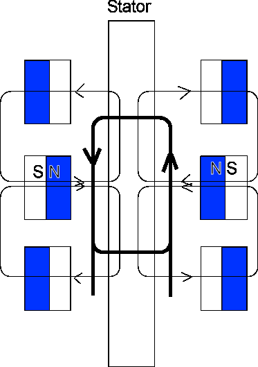


I hope I used the right hand rule in the correct manner, (might have switched the Ups and downs)if not then I'll apologize, but the principle described above is a good way of showing what goes on in the toroid.


Hope that helps, let me know if you need more infos.


Powerbuoy

« Last Edit: May 20, 2006, 10:29:21 AM by powerbuoy »

ghurd

  • Super Hero Member Plus
  • *******
  • Posts: 8059
Re: google video
« Reply #6 on: May 20, 2006, 09:58:40 PM »
"switched the Ups and downs". So what? It's the same for AC. I use arrows too. Fast and simple.
« Last Edit: May 20, 2006, 09:58:40 PM by ghurd »
www.ghurd.info<<<-----Information on my Controller

willib

  • SuperHero Member
  • ******
  • Posts: 2414
  • Country: us
Re: google video
« Reply #7 on: May 20, 2006, 10:44:46 PM »
so would the magnets be comming out of the page in your diagram?

they woud have to , to cut across the coils

you didnt answer my question , did you try opposite poles on each rotor? ie a standard rotor configuration?
« Last Edit: May 20, 2006, 10:44:46 PM by willib »
Carpe Ventum (Seize the Wind)

ghurd

  • Super Hero Member Plus
  • *******
  • Posts: 8059
Re: google video
« Reply #8 on: May 20, 2006, 11:35:00 PM »
The diagram is beginning to look like 1/2 a transformer wound on the center leg of a 3 leg transformer.


In the following post...

http://www.fieldlines.com/story/2005/9/2/15582/32487


G-

« Last Edit: May 20, 2006, 11:35:00 PM by ghurd »
www.ghurd.info<<<-----Information on my Controller

willib

  • SuperHero Member
  • ******
  • Posts: 2414
  • Country: us
Re: google video
« Reply #9 on: May 21, 2006, 12:02:18 AM »
not quite , imho

your diagram the coils are horizontal to the magnet faces ,

in his diagram , and in the torus , the coils are vertical to the magnet faces.

but i still think it will work ,my way , because there would be a north cutting one side of the coil , and a south cutting the other side ,

 with no core , it would not work.

but with a core i think it would  work

« Last Edit: May 21, 2006, 12:02:18 AM by willib »
Carpe Ventum (Seize the Wind)

ghurd

  • Super Hero Member Plus
  • *******
  • Posts: 8059
Re: google video
« Reply #10 on: May 21, 2006, 01:14:21 AM »
IMHO, it is exactly the same. (Core or no core)


I can not eloquently explain my perspective.  It seems I just wore the rest of the ink off the `backspace' key.


However, Mr. Flux often refers to it as coils being linked, often pertaining to use in a laminated core or AC motor conversion.

Compare all he said about linking coils, to my sketch if it was doubled, in mirror image.


Maybe look at powerbuoy's diagram from the transformer prospective.

The magnetic field in a transformer never actually crosses the coils. The field only varies inside or outside the coil. Magnetically many people can't see how one works compared to a normal wind machine shown here.

Next,

Relate that to slotted cores. Turn the slotted cores sideways, if you want, but I see no reason to unless it helps you see the concept.  

Radial to axial, or axial to radial kind of thing. I don't see any difference, conceptually speaking..


I typed my ass off.  That's the best I can do.

« Last Edit: May 21, 2006, 01:14:21 AM by ghurd »
www.ghurd.info<<<-----Information on my Controller

powerbuoy

  • Full Member
  • ***
  • Posts: 208
Re: google video
« Reply #11 on: May 21, 2006, 06:43:02 AM »
I drew it up in a different way, it shows better how the flux goes and how it hits the coils ...Let me know what you think ... looks big but its only a couple kilobytes ...:-))


Powerbuoy


« Last Edit: May 21, 2006, 06:43:02 AM by powerbuoy »

willib

  • SuperHero Member
  • ******
  • Posts: 2414
  • Country: us
Re: google video
« Reply #12 on: May 21, 2006, 06:46:21 AM »
Ghurd ,i just rethought powerbuoys your righthand rule explaination , it seems to make sense, i think

i would like to  experiment , just to make sure though.

sorry if i made you type more than you wanted to , i hate typing too
« Last Edit: May 21, 2006, 06:46:21 AM by willib »
Carpe Ventum (Seize the Wind)

powerbuoy

  • Full Member
  • ***
  • Posts: 208
Re: google video
« Reply #13 on: May 21, 2006, 06:57:04 AM »
Also, I forgot ...there are two potential advantages with this design. No 1 ...in a typical pancake design (like the brake drums) you'll have the coil ends which are not being hit by a magnet, therefore they are just dead wire resistance. In this donut configuration the coil ends are short.


No.2 ...look how many coils you can wind on the donut. You can easily put 36 side by side on this unit ...


Drawback might be heat. You see, the donut has the highest display of flux density and the heat has to pass the coils to get out. But, maybe this is a very efficient design and will not produce too much, worth a try. I built mine with pride, ...but used way to weak plates, too large distances and so on. Maybe its time for an upgrade ...


Anyway, ... we have seen the brakedrums for a while now and there are some people here on the board who have them figured out a 100%. Maybe the toroid can push us into a new direction, once in a while one should try something new. If someone can pull it off then it's this board.


Powerbuoy

« Last Edit: May 21, 2006, 06:57:04 AM by powerbuoy »

willib

  • SuperHero Member
  • ******
  • Posts: 2414
  • Country: us
Re: google video
« Reply #14 on: May 21, 2006, 07:56:34 AM »
Yes ! i agree the number of coils is an advantage for sure


i dont see heat a that much of a problem , what were the specifics of your toroid?

like stator thickness? with and without coils

distance from magnets to core ,

wire dia.?

number of coils , number of turns , number of layers of wire ,

dia of core ect.

anything you can provide will help,

« Last Edit: May 21, 2006, 07:56:34 AM by willib »
Carpe Ventum (Seize the Wind)

ghurd

  • Super Hero Member Plus
  • *******
  • Posts: 8059
Re: google video
« Reply #15 on: May 21, 2006, 10:11:38 PM »
Still looks 'the same' to me, in principle. At least it won't cog!
« Last Edit: May 21, 2006, 10:11:38 PM by ghurd »
www.ghurd.info<<<-----Information on my Controller

ghurd

  • Super Hero Member Plus
  • *******
  • Posts: 8059
Re: google video
« Reply #16 on: May 21, 2006, 10:25:56 PM »
I did some playing with the half of a transformer. It worked.

Never went farther than some small magnets on the drill press at low RPMs.  

One transformer probably weighs more than a small motor conversion. A completed unit full of transformers would weigh a ton.


Then some of the comments (from the link) started sounding like it would end up being a bigger stepper motor, with all the same problems. I stopped right then.


I wanted to say more last time, just couldn't figure out how to say it!

G-

« Last Edit: May 21, 2006, 10:25:56 PM by ghurd »
www.ghurd.info<<<-----Information on my Controller

ghurd

  • Super Hero Member Plus
  • *******
  • Posts: 8059
Re: google video
« Reply #17 on: May 21, 2006, 10:29:41 PM »
"number of coils , number of turns "

Maybe... there are no tops and bottoms, only legs?  All the coil is active? Less turns?

Just a thought. Not sure.

G-
« Last Edit: May 21, 2006, 10:29:41 PM by ghurd »
www.ghurd.info<<<-----Information on my Controller

powerbuoy

  • Full Member
  • ***
  • Posts: 208
Re: google video
« Reply #18 on: May 23, 2006, 08:08:40 PM »
give me some days to dig it up ... the parts are all over the place.


so far from what I recall.


The magnets:


12 on each plate 1" x .5" x .25  total 24


diameter toroid OD I believe is 9", ID is 7"  


windings, 36 coils, 45 windings, AWG22


RPM roughly 500


voltage star 46V open


amps shorted 2.5A

« Last Edit: May 23, 2006, 08:08:40 PM by powerbuoy »

willib

  • SuperHero Member
  • ******
  • Posts: 2414
  • Country: us
Re: google video
« Reply #19 on: May 23, 2006, 11:53:49 PM »
was the core laminated?

if so what was the orientation of the laminations  ?


there is a material , whose name unknown to me , that goes around the  neck of a picture tube , pc monitor whatever,the deflection coils are wrapped around this stuff , its a lot like the core of an inductor

and this material is magnetic ,

the interesting thing about it is it is omnidirectional ,ie unlike a laminated core whose flux depends on the angle the  magnetic field is hitting it, or i should say the orientation of the laminates determine how the flux is propagated

 i think it would make a good  core material

« Last Edit: May 23, 2006, 11:53:49 PM by willib »
Carpe Ventum (Seize the Wind)

powerbuoy

  • Full Member
  • ***
  • Posts: 208
Re: google video
« Reply #20 on: June 03, 2006, 09:27:07 AM »
I used steel bands, rolled up with insulation between....veeeerrrryyy crude approach.
« Last Edit: June 03, 2006, 09:27:07 AM by powerbuoy »