Author Topic: The Permogator Saga (cont'd)  (Read 4461 times)

0 Members and 1 Guest are viewing this topic.

Chester

  • Jr. Member
  • **
  • Posts: 55
The Permogator Saga (cont'd)
« on: August 03, 2004, 09:26:45 PM »
Here's a photo of Permogator 1.


Tested the tachometer and found it was spinning about 650 RPM. Way more than I thought. The tach works good. It generates a laser beam and counts reflections from a little piece of shiny tape you have to stick on what it is you want to measure.


I rebuilt the bearing, using some roller skate parts. The abec 7 bearing made a nice hub and the plastic spacer fit nicely around the 1/4 in shaft, resting on the inner ring of the abec 5 bearing (1/4" bore, 5/8 diameter) that was inserted into a nylon shaft collar, glued to the unit. One thing I don't like about it is the set screw. From now on I'm using aluminum, one piece shaft collars, which fit around the bearing evenly and don't torque it on one side.


Nevertheless, hardly any friction on this set up. RPMS went to 950 with the same input. I added two more AA  batteries in series and coaxed it up to 1250 rpm. That generated 1.7 volts!


I ran an endurance test with two 1800 mAhr and two 2100 mAhr batteries. Average rotation for 8 hours was 941 RMP, average output volts were 1.48. At 8 hours and 10 minutes the batteries output was 4.4 volts, which wasn't enough to fire the 555 chip and ended the test. Based on my previous calculations, 1800 mAhrs times 4 batteries is 7200 mAhrs used. 8459 mAhrs were generated. Efficiency, threfore, on this test is over 117%. I think that is conservative, since I didn't drain the batteries completely. So, I found this encouraging.


Received the Kikusui 5630 oscilloscope I bid on at EBay and it works. I contacted the factory for a manual. They let me download on from their server in pdf format, which I printed out. Then I ordered two 60 Mhz probes from All Electronics for 19 dollars each. So now I have a working dual trace 60 Mhz oscilloscope for 150 bucks. It's way more than I need.


The next comment will have a trace diagram.

« Last Edit: August 03, 2004, 09:26:45 PM by (unknown) »

Chester

  • Jr. Member
  • **
  • Posts: 55
Re: The Permogator Saga (cont'd)
« Reply #1 on: August 03, 2004, 09:42:34 PM »
Since I was generating more power, I installed an LED on the output legs and it lit easily, in either polarity. So, it's an alternator. I thought with all the magnets pointing the same way, I would get DC pulsed current. But, what do I know? Nothing, is the right answer.


Here then is the new schematic:


Using both channels of the Kikusui 5630, I tapped in at B and C. Here is the drawing of the image that appeared on the scope.


The blue trace is at B and the red trace at A. Freshly charged batteries had the RPMs up to 1015 at start.


I don't know what to make of it. The sinusoidal wave on the alternator looks nice. The motor circuit looks all confused and not what I expected. First the 555 pulse is way faster than the specs for the chip say it should be, using the R1 and R2 values I have. Those calcs return about .002 mHz, or 2 Hz.


Can someone help me here. What's happening?

« Last Edit: August 03, 2004, 09:42:34 PM by Chester »

finnsawyer

  • Hero Member
  • *****
  • Posts: 1565
Re: The Permogator Saga (cont'd)
« Reply #2 on: August 04, 2004, 10:41:05 AM »
Where did you connect the ground lead?  I.e. What voltages specifically are you measuring.  Since you have a circuit with energy storage devices (inductors; capacitors) its not easy to determine power in and power out.  For instance, the energy stored in a capacitor is a function of the voltage:  E = 1/2CV^2.  Again, check my posting on Bedini Motors for a discussion how to use this.  You can determine the energy in, however, by putting a small resistor in series with the battery to measure the current.  Plot the product of battery voltage times that current versus time (seconds).  The area under that curve is the energy in.  Do a similar thing for the load.  The pulsing nature of the waveforms is going to make this difficult, but that's life.  You need to find the energy per pulse and then multiply by the number of pulses per second to get each data point.
« Last Edit: August 04, 2004, 10:41:05 AM by finnsawyer »

Chester

  • Jr. Member
  • **
  • Posts: 55
Re: The Permogator Saga (cont'd)
« Reply #3 on: August 04, 2004, 06:34:18 PM »
The ground lead on channel one (the motor) was connected at point 4 and the other lead connected at point 3. (3,4) in my new scheme is called B. (1,2) is A and (5,6) I now call C. It's simpler to type and keep my notes with.


Sorry I wasn't clear about the July 29 test.


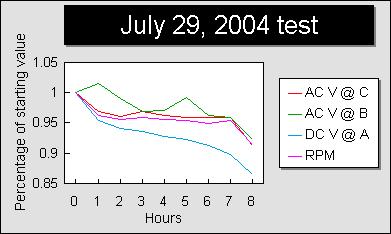
I kept hourly track of the readings at points A, B and C and the RPM. A gives the current battery voltage. B is between the coils and the 555 chip in the motor circuit and C is on the alternator circuit at the LED load. All the readings were made with a multimeter. The RPMs were made by tachometer.


Here are the readings for each hour.


July 29, 2004 test               

Hour   AC@ C   AC@ B   DC@ A    RPM


  1.     1.54    1.31    5.42    985
  2.     1.49    1.33    5.17    948
  3.     1.48    1.30    5.10    942
  4.     1.49    1.27    5.07    945
  5.     1.48    1.27    5.03    942
  6.     1.48    1.30    5.00    939
  7.     1.48    1.26    4.95    935
  8.     1.48    1.26    4.87    940
  9.     1.41    1.21    4.69    900


avg    1.48    1.28    5.03    941.8


ten minutes later DC@ A was 4.4 volts. End of test.


Summary of Readings averages


At    Volts    Ohms    Amps    Watts

A    5.03    13700       

B    1.28    1.4    .913    1.17

C    1.48    1.4    1.057    1.57


Power usage.

4 batteries @ 1800 mAhrs each total 7200 mAhrs       

used for 8 hours or at the rate of   900  mA/hour MAX   


Power provided by the free ride alternator coils.

Output at C=8 hours generated at    1057 mA/hr

For a total of                      8459 mAhrs   


                    117.49%    efficiency   


Here is a graph of the percentage declines from the start to the end.


The only capacitor in the system is related to the 555 chip and sure, all of the coils are inductors. But their very nature is that they store and release power and do not comprise a load, correct? So the only load on the input for the motor is in the resistors that control the 555 capacitor.


As far as determining the energy in, I have done that. It's the mAhr usage of the batteries, right?


They only thing I wanted to compare was an apples to apples situation. The mAhr calculation for the output at C is questionable to me, because I don't know for sure, if AC Volts and the Resistance of that circuit make amps that are directly comparable to the input amps of the batteries. If they are, then the efficiency measured should be valid.


Since I am using the maximum value of the battery discharge into the motor, then the only thing I might accomplish by trying to measure the minute energy of individual cycles would be greater efficiency, correct? Not that I'm adverse to doing those calculations, but since I know the maximum usage, all I need to do is find the total number of cycles over the eight hours and apply arithmetic to come up with the answer, right?


I had a couple of typos in the previous post about the points of measure. I hope this posts corrects those. Remember, the red trace in the scope image is channel two, measured at point C OF THE ALTERNATOR. The blue trace is channel one at point B of THE MOTOR.  

« Last Edit: August 04, 2004, 06:34:18 PM by Chester »

Chester

  • Jr. Member
  • **
  • Posts: 55
Re: The Permogator Saga (cont'd)
« Reply #4 on: August 04, 2004, 06:40:20 PM »
Motor function.


Each revolution of the rotor, energizes the coils 8 times, since there are eight coils and eight magnets equally spaced.                                           

When the batteries are powered into the system, the coils attract the magnets. The magnets move to the center of the coils. (They can also be set to repel, by reversing the polarity of the leads, but seem to work better in attraction mode).                                           

The 555 chip is pulsing DC very rapidly, on and off while the magnets are centered over the coils and a high pitched tone is generated. There appears to be two pulses, one positive from the battery and another negative from the capacitor on the scope. The DC on the square wave release is about 3.5 volts, and the volts from the capacitor release about 1.7. Their combined voltage is very near the constant input of the batteries.    This seems consistent with the NS specifications, that in this mode the capacitor charges and discharges between 1/3 VCC and 2/3 VCC. It appears to me that the capacitor discharge is about 1/3 of the total discharge. But I'm not sure.


Spinning the rotor by hand gives it the momentum to carry the magnets installed in it, over the coils. The magnets, of course, energize the coils as they pass over them. The tone is no more, but there is subduded and much lower pitched hum.                           

If spun fast enough a resonance develops and the rotor speed ramps up fairly rapidly, to where I suppose it can no longer overcome the friction of the bearing.                                           

Currently the rpms hold at about 950. The variables here appear to be voltage and bearing friction, since I know more voltage will spin it faster. I think larger magnets would speed it up as well, but for now that is a constant.                                           

As the magnets pass over the center and then between the coils, an oscillating current is generated. The magnets and coils generate a sinusoidal wave that appears to modulate the DC voltage.                                           

The negative part of the AC wave appears to counteract the DC pulses and they don't appear on the scope, during half the AC cycle. This also may serve to reverse the coil polarity, repelling the magnets as they pass beyond the center and edge of the coil. Well, something does make it go around!


As the magnets pass beyond the edge of the coils and return towards their centers the AC wave turns positive allowing the DC pulses to energize the coils, which then attracts the magnets with enough force to maintain the rotor momentum. And round and round she goes.


The alternator coils on the other stator, get a free ride here. There is no additional friction to overcome as would be necessary if they were in a separate device. No additional magnets are necessary to employ, either.


Knowing the rpm, one should be able to determine the frequency of the wave. It should be rpm times 8 divided by 60 seconds.                           

At an rpm of 950 times 8 coils,    a frequency 7600 cycles    per min or 126.7 hertz (oscillations per second) is calculated.


Since a 25 ms cycle is equivalent to 40 hertz, then 126.7 divided by 40 times 25    is 79.17 ms per cycle by the rpm.               


The scope shows the frequency of the AC wave to be about 8 ms per cycle. Within 1/2 of the AC wave cycle, the 555 chip is pulsing 10 times or 20 times per cycle, though you can't see the pulses when the wave is negative.


There is a discrepancy in the two readings of ms per cycle that seems off by a factor of about 10! Duh!


I checked all the settings on the scope and probe and they all appear to be correct, so I can't account for this. The probes are set for 1x, and the scope for 2 ms per division, the volts for each channel are 1 volt per division. What am I missing?

« Last Edit: August 04, 2004, 06:40:20 PM by Chester »

finnsawyer

  • Hero Member
  • *****
  • Posts: 1565
Re: The Permogator Saga (cont'd)
« Reply #5 on: August 04, 2004, 09:18:03 PM »
Puzzles me why you didn't put the scope on the output since you are claiming a power gain.  I suggest you do so to see what kind of waveform you're getting.  


Inductors also have resistance and do consume power.  You can measure the resistance of your coils by using an ohmmeter.


An ac voltmeter only measures accurately for sinusoidal waveforms with no dc component.  In general pulse trains will give erroneous readings.


Battery amphour ratings are given for certain rates of drain.  They are no substitute for measuring the actual current.


Power (joules/second) is given by volts times amps only when the voltage and current are in time phase.  With inductors in the circuit they are probably not in time phase.  Read up on this.


The difference in frequencies may be simply due to the fact that the 555 is triggering the "motor" faster than it can run.  Slow the 555 down and see what happens.


What you will accomplish by following the procedure I gave is greater accuracy and believability.  If you were going to submit your findings to a scientific journal this is what you would have to do.

« Last Edit: August 04, 2004, 09:18:03 PM by finnsawyer »

sh123469

  • Jr. Member
  • **
  • Posts: 56
Re: The Permogator Saga (cont'd)
« Reply #6 on: August 04, 2004, 10:53:39 PM »
I suspect that there is something somewhere that you have not taken into account.  According to your figures, you have managed to get more power out than you have put in.


Considering the mechanical losses, you are, in overall efficiency, well over the stated 117% electrical efficiency.


In sincerely hope that you have managed this feat for the sake of the world's energy problems.  But, I suspect that there is a flaw in your measurements somewhere.  If not a hearty congratulations is well in order.


Steve

« Last Edit: August 04, 2004, 10:53:39 PM by sh123469 »

finnsawyer

  • Hero Member
  • *****
  • Posts: 1565
Re: The Permogator Saga (cont'd)
« Reply #7 on: August 05, 2004, 06:41:59 AM »
Note that the ground leads for the three channels of the scope are probably connected together internally.  If so, you need to be careful how you connect the scope so you don't short out across the circuit.
« Last Edit: August 05, 2004, 06:41:59 AM by finnsawyer »

Chester

  • Jr. Member
  • **
  • Posts: 55
Re: The Permogator Saga (cont'd)
« Reply #8 on: August 05, 2004, 12:12:00 PM »
Duh. Sometimes I don't know what I'm thinking. If 1000 divided by 40 Hz yields 25 ms, and it does, then 1000 divided by 126.7 Hz yields 7.89 ms. Scope is therefore in synch with the RPMs and they're both right. My bad.
« Last Edit: August 05, 2004, 12:12:00 PM by Chester »

Chester

  • Jr. Member
  • **
  • Posts: 55
Re: The Permogator Saga (cont'd)
« Reply #9 on: August 05, 2004, 12:27:57 PM »
Actually, the red trace is the output sine wave. Sorry that isn't clear. There are two circuits; the motor circuit is the blue trace and the red trace is the alternator output trace. It is a very clean sine wave and there is no DC intermixed with it. They are shown overlaying each other, just because I didn't want to upload two drawings.


The motor coils and alternator coils are identical in size and in number and in spacing, except that one set is placed on its respective stator halfway between the other set. Their only connection is the magnets spinning between them on the rotor. I spaced them to eliminate induction of one to the other. There is some very minor leakage, even so; a few millivolts, which is to be expected. I do have a ohm function on my multimeter and did measure the ohms in the wire of each assembly and that returned 1.4 ohms in the both sets of eight the coils wired in series. This is shown in the Summary of the July 29 test. I also should mention I ran the test without the LED load on the alternator circuit.


Well, I guess before I submit this to a science journal, I'll get it tested by several other people in what ever manner they choose. Interested?

« Last Edit: August 05, 2004, 12:27:57 PM by Chester »

Chester

  • Jr. Member
  • **
  • Posts: 55
Re: The Permogator Saga (cont'd)
« Reply #10 on: August 05, 2004, 12:31:31 PM »
There are but two channels in this scope. Thank GOD!
« Last Edit: August 05, 2004, 12:31:31 PM by Chester »

Chester

  • Jr. Member
  • **
  • Posts: 55
Re: The Permogator Saga (cont'd)
« Reply #11 on: August 05, 2004, 09:43:22 PM »
I slowed the 555 chip to the extent I am able. I need bigger resistors to do more damage. Now I have three 20k pots connected in series maxed. I may go to radio shack in the morning.


The problem with me testing the current at present, is my meter will self destruct over 400 mAmps, according to the manual. Since I am quite sure I there are more milli amps in either circuit, I elect not to destroy my meter.

« Last Edit: August 05, 2004, 09:43:22 PM by Chester »

Chester

  • Jr. Member
  • **
  • Posts: 55
Re: The Permogator Saga (cont'd)
« Reply #12 on: August 05, 2004, 09:48:20 PM »
Darn near forgot to tell you what happened when I slowed the 555.


I got it down to 6 beats from 10 beats per semi cycle. The rmps went from a sustainable 950 to 1030. The output volts at C went to 1.533. I suspect the batteries are not working as hard, as well.

« Last Edit: August 05, 2004, 09:48:20 PM by Chester »

wooferhound

  • SuperHero Member
  • ******
  • Posts: 2288
  • Country: us
  • Huntsville Alabama U.S.A.
    • Woofer Hound Sound & Lighting Rentals
Re: The Permogator Saga (cont'd)
« Reply #13 on: August 06, 2004, 06:45:33 AM »
He is using an AC meter setting to measure odd waveforms and frequencies.


I would run the output through a bridge Rectifier (some loss there) and then measure the voltage.

« Last Edit: August 06, 2004, 06:45:33 AM by wooferhound »

DanB

  • Global Moderator
  • SuperHero Member
  • *****
  • Posts: 2151
  • Country: us
    • otherpower.com
Re: The Permogator Saga (cont'd)
« Reply #14 on: August 06, 2004, 08:47:25 AM »
Id say... "by George I think he's got it..."


only after you figure out how to charge the battery that runs it so it runs on it's own accord.  Amazing how many folks have built "overunity" machines... yet nobody's quite managed to get them to run themselves yet.


Call me a skeptic, but Im quite certain it cannot be done.  Neat project though - and vedry good pictures, and a very good discussion of a popular topic.  Thanks for sharing!

« Last Edit: August 06, 2004, 08:47:25 AM by DanB »
If I ever figure out what's in the box then maybe I can think outside of it.

finnsawyer

  • Hero Member
  • *****
  • Posts: 1565
Re: The Permogator Saga (cont'd)
« Reply #15 on: August 09, 2004, 11:21:29 AM »
It sounds like you know about mutual inductance, so I'll skip that.  As far as the power or energy measurements, I'd like to suggest the following.  Replace the led by a carbon resistor and place a small 1% resistor (one ohm?) in series with the negative battery terminal.  Now take your scope, put both amplifiers in dc mode  and put the ground leads at the connection between the battery and the one ohm resistor.  Put one input to measure battery voltage and one to measure the resistor voltage.  This gives battery current by dividing the voltage as read off the scope (must be calibrated) by the resistance.  Is the battery voltage constant or does it have ripple?  It should be constant.  Now power out from the battery is the product of the battery voltage and the current out at a given time (instantaneous).  In general power for a device can be positive or negative depending on whether it is putting out or absorbing energy at that time.  Make a drawing of the current curve for one cycle.  Scale it to power by multiplying the correct scale value for current by the value of battery voltage.  Determine the area under the curve for one cycle in units of volt-amps-sec.  This is the energy in joules out from the battery per cycle.  Now disconnect the ground leads and put one scope input (both leads) across the output resistor.  Since voltage and current are in phase for a resistor the power absorbed by it is always positive and is V^2/R.  So make a plot of the the resistor voltage squared divided by R for one cycle.  The area under the curve is the power consumed by the resistor for one cycle.  If the time per cycles are different you need to adjust your results so they cover the same time period.  I.e.  if the first has five cycles versus one for the other multiply the first result by five.  While there are potential pitfalls this procedure should give you the true power ratio.
« Last Edit: August 09, 2004, 11:21:29 AM by finnsawyer »

Chester

  • Jr. Member
  • **
  • Posts: 55
Re: The Permogator Saga (cont'd)
« Reply #16 on: August 10, 2004, 04:37:07 PM »
I may have mentioned, I am rather new at this, and I don't understand exactly what calculations you are asking. Here are the scope images with the connections you describe. The top trace is across the battery and I installed a one ohm resister in series on the ground. It looks like this:


The top panel is with the power on, but the rotor is not spinning. The bottom panel has the rotor spinning. If you are able to decipher an amp reading from this, I certainly would be interested in following your logic and calculations. By multimeter readings the battery channel returns 4.68 Volts with no rotor spin and 4.86 Volts with it spinning. The one ohm resistor returns 345 mV either way. It appears to be 1/2 Volt on the scope and negative as you can see.


I've known for some time that the alternator will stop when I short the leads, and putting a very small value resistor there stops it as well. It will continue to rotate, though at a reduced speed with a 10 ohm resistor. It slows to about 500 RPM and produces 500 mVolts. So, do you measure fuel consumption in a new car by attaching it to a 9 bottom plow?


I did some research on how AC voltmeters work and I think the one I have works this way. It has a bridge rectifier or Op Amp circuit that converts the AC current to DC, then measures the magnitude and multiplies that out by .707. Thereby coming to an average DC voltage due to the half ellipse of the wave. If that is true, then the AC voltage is in DC terms and the input and output I am measuring are apple to apple.


I'm calculating the output power under no load conditions for my efficiency test. That should have been obvious from the start. Certainly if you add different loads you will get different results.


If I put a 10K ohm resistor load in place of the LED, there is no obvious reduction in the RPMs of the rotor. If I put a 10 ohm resistor in place of the LED, there is a dramatic fall off in RPMs. If I put a LED in series with the 10 ohm resistor there is no fall off. Weird, huh?


I also want to address some of the comments that other people have graciously taken the time to post. I don't think this is the answer to the energy problem, but I haven't finished convincing myself, since I am learning more and more with each passing day. I hope to build a circuit on the output to rectify and perhaps amplify the current so that it is usable. Perhaps to power another permogator, or if by some extraordinary stroke of luck, itself. I have some parts on the way, one of which is a 741 Op Amplifier chip. Anyone ever try to build a rectifier with one of these? Finally, I think this device is a rather crude and inefficient prototype of what might be built, so I'm not giving up yet. I'm experimenting with a passive magnetic frictionless bearing. I hope to pass or fail that in the next couple of weeks.


Again, thank you all for you comments. It helps to know that folks are interested.

« Last Edit: August 10, 2004, 04:37:07 PM by Chester »

nack

  • Jr. Member
  • **
  • Posts: 65
Re: The Permogator Saga (cont'd)
« Reply #17 on: August 10, 2004, 06:07:00 PM »
Use a shunt resistor for measuring current.
« Last Edit: August 10, 2004, 06:07:00 PM by nack »

TomW

  • Super Hero Member Plus
  • *******
  • Posts: 5130
  • Country: us
Re: The Permogator Saga (cont'd)
« Reply #18 on: August 11, 2004, 02:15:37 AM »
Chester;


I did some research on how AC voltmeters work and I think the one I have works this way. It has a bridge rectifier or Op Amp circuit that converts the AC current to DC, then measures the magnitude and multiplies that out by .707. Thereby coming to an average DC voltage due to the half ellipse of the wave. If that is true, then the AC voltage is in DC terms and the input and output I am measuring are apple to apple.


I can't say whether the part about AC voltmeters is true or in which meters this applies.


The problem arises when you are either measuring Wild AC or measuring an AC waveform that is either well above or below the expected frequency  rating of the meter in question as well as duty cycle of the waveform,  non sinusoidal waveforms like sawtooth, stepped or square waves. All of these things affect the so called "average" voltage your meter sees. So, sorry to have to tell you, it is not apples to apples.  The .707 figure  applies to a sinewave only, also.


Just some very basic stuff I thought I should mention. Just tossing it out so you can understand why you cannot compare the two directly.


T

« Last Edit: August 11, 2004, 02:15:37 AM by TomW »

commanda

  • Hero Member
  • *****
  • Posts: 731
Re: The Permogator Saga (cont'd)
« Reply #19 on: August 11, 2004, 02:28:02 AM »
You need a "true RMS" meter. I have 2 Flukes, model 79 & 179. But you also need to be aware that all AC measuring devices have some frequency beyond which they are no longer accurate.


Amanda

« Last Edit: August 11, 2004, 02:28:02 AM by commanda »

finnsawyer

  • Hero Member
  • *****
  • Posts: 1565
Re: The Permogator Saga (cont'd)
« Reply #20 on: August 11, 2004, 10:56:14 AM »
First I'd like to point out that if you have no load you have no output power.  Why?  No load means no output current.  Zero times any voltage is zero.  That's why you need to hang a resistor on the output.  The effects due to different resistors are to be expected.  The led effect is not necessarily weird as an led may have an internal resistance in series with its light emitting diode.


You would run tests on a car with a dynamometer, which corresponds to a load resistance in your circuit.  Unless your device can provide energy to an external load it's totally useless.  A car provides mechanical energy to the road for example.


Expand the current trace by going to 1 or .5 volts per division (calibrated).


Now the power calculation.  Your trace shows a lower frequency waveform imposed on the input which is probably feedback from the output (stray 60 cycle can also cause such a trace).  Since that's a lower frequency than the pulse train that becomes the cycle to use.  Even so, you're lucky, because when the battery voltage is high the current is zero.  No power out.  You only need to calculate the power for a non zero current.  So multiply the voltage for each current providing pulse by the current for that pulse and by the time duration of the pulse (in seconds).  I see seven such pulses.  Add them up and you have the energy provided by the battery per cycle.  Now the cycle I'm using is from the beginning of the trace to the end of the flat zone (hopefully the output frequency).  It's 8.4 msec long.  Do the same for the output resistor.


For the first pulse I read a voltage of 4.4 volts, a current of .6 amps (.6 volts divided by one ohm), and a time of .6 msec. total energy = .00158 joules.  Do the same for the other six pulses and add the results.


It would have helped if you had shown a trace of the output at the same sweep setting.  I'm concerned about 60 cycle leakage.  Since you are claiming a power (energy) gain you should show the input and output traces for some reasonable values of resistance.  Yeah, the ten ohm would be fine.    

« Last Edit: August 11, 2004, 10:56:14 AM by finnsawyer »

Chester

  • Jr. Member
  • **
  • Posts: 55
Re: The Permogator Saga (cont'd)
« Reply #21 on: August 11, 2004, 02:48:21 PM »
Okay, thanks. But, since I am generating a regular sinusoidal wave, albeit at a frequency of about 125 Hz, when the scope shows it to have a magnitude of ~2 volts, the reading on my meter is ~1.414. The reading may just be an approximate, but my Radio Shack meter manual does claim the AC voltages I'm getting to be within the range of operation of the meter. Not that it is a extremely expensive meter.    
« Last Edit: August 11, 2004, 02:48:21 PM by Chester »

Chester

  • Jr. Member
  • **
  • Posts: 55
Re: The Permogator Saga (cont'd)
« Reply #22 on: August 11, 2004, 03:26:20 PM »
Points on power taken and understood. Here is the scope image with the alternator trace superimposed over the two DC traces from the motor.


I reran the test, since I now see what you are looking for more clearly. This drawing is now diagramatic since I don't get exactly the same readings every time I run the device. I hope you understand this is because the device is fairly crude in precision.


This time I see 8 pulses in train instead of 7. This I assume to be because the load of the alternator resistor slowing the unit slightly. This resistor measures 98.9K ohms.


The pulse train must be caused by the 555 chip, since the timing of the beats are identical. The wave cycle seems to be feedback from the induction coils as the magnets pass over them generating an alternating current in the motor. It should have very minor leakage to the alternator, however, as you can see the two currents are 90 degrees out of phase from each other and stand pretty much on their own.


GeoM wrote: >>For the first pulse I read a voltage of 4.4 volts,<<


I'm with you so far. I see that too!


>>a current of .6 amps (.6 volts divided by one ohm),<<


I don't see where you came up with the .6 volts. Are you looking at the 1 ohm trace for this figure? If so, it measures .5 volts by zooming in on the scope.


I do see how you derive the amps: Ohms Law.


>>and a time of .6 msec.<<


I was able to zoom in very close to the trace. The length is .5 msec and the time between the pulses is .1 msec. This appears to be a function of the 555 chip.


>>total energy = .00158 joules.


Help me out here. What is the formula you used, for the record?


>>Do the same for the other six pulses and add the results.


Why not just multiply by the number of pulses?


RPMs on this test were 988. One cycle therefore is 7.59 msec. I hope you can excuse the inaccuracy of the drawing.


Sorry I sound so ignorant about this. I really do need all the help I can get.

« Last Edit: August 11, 2004, 03:26:20 PM by Chester »

finnsawyer

  • Hero Member
  • *****
  • Posts: 1565
Re: The Permogator Saga (cont'd)
« Reply #23 on: August 11, 2004, 09:12:12 PM »
Energy (joules) = voltsxampsxtime = 4.4x.6x.0006 = .001584.  The numbers I used were the best I could read off of the trace.  I still count 7 pulses (the negative values of the  current waveform).  I didn't suggest multiplying by 7 as the battery voltage changes slightly during the time of the output waveform.  Multiplying by 7 gives you .o11 joules, an estimate.  If you divide by the time of the output cycle .0084 sec you get the average power, 1.3 watts.  I'll let you work out the power or energy going into the 98.9 kohm resistor.  I predict it will be less than the power provided by the battery.  Have fun!  
« Last Edit: August 11, 2004, 09:12:12 PM by finnsawyer »

jacquesm

  • Sr. Member
  • ****
  • Posts: 467
Re: The Permogator Saga (cont'd)
« Reply #24 on: September 09, 2004, 04:22:08 PM »
first of all, let me compliment you on the beautiful execution of your idea.


You've done a fantastic job at this, much better than most pros that I know at building a test setup of a new device.


There is one little error (but alas for you, big enough) in your calculations: An oscilloscope 'measures' (it doesn't really measure it just shows, you do the measuring by counting grid lines) 'Peak' voltage. An AC meater measures "RMS" (root-mean-square) within a very narrow frequency range. A DC battery discharges over time and it's voltage will drop, so the current will drop. A battery's rating in 'AmpHours' is a rough indication of the capacity of that battery, not how much it actually stores right now. (just as a 1 liter bottle may be more or less full, never fuller than 1 liter though!)


Your device consumes power while it is running (the batteries running down pretty much proves that), and some of that power (but not all, but you did a pretty good job on keeping friction and drag down, so quite a bit, possibly as much as 80+%) makes it to your output. But it's not 'DC' current that you can compare in a numerical way with the DC current that you have put in. You need to measure produced power over time exactly. For that you would need a 'calorimeter'. This is a device that converts the power that you make into heat, and then precisely measures the temperature difference. You may then compare apples with apples by directly discharging your battery into the calorimeter and by running a second session (with an exact same charge in your batteries to begin with) using your 'motor/generator' setup. In the second run you will find a slightly lower power production. The difference between the two runs can be explained by the audible and heat losses (due to little bits of friction in your bearing) and aearondynamic drag.


For a quick improvement on the runtime of your little machine try putting it under an evacuuated glass dome ! You'll be amazed at the improvement. Even a flat disc with hardly any protrusions creates quite a bit of drag (this is because the air particles that come close to the disc are swirled outward by centrifugal forces, only to be replaced with new particles and so on).


best regards,


  Jacques

« Last Edit: September 09, 2004, 04:22:08 PM by jacquesm »

devoncloud

  • Jr. Member
  • **
  • Posts: 82
Re: The Permogator Saga (cont'd)
« Reply #25 on: September 12, 2004, 05:42:26 PM »
(copied from another post)

"Chester, your new permogator machine has not proven to be a unity or overunity machine.  In fact, it has proven nothing except you built a small efficient alternator.  Plug the electricity you are creating with the unit back into the machine (perhaps with some resistors so you can limmit the input of power you are putting into your alternator so that you do not spin your machine out of conrol) and see if it is indeed able to create more energy than it requires to run it by removing your batteries after the machine is running, and see if it truly can run itself with the electricity it creates.  

If it is indeed an overunity machine, you will no longer need the batteries, correct?  This is what I am talking about here.... it would be very easy to test the theory that you have created an OU machine Chester.... you just need to do it with this very easy test, and you have not done this easy test, which tells me you do not want to for some reason, which tells me it is because you know that it is not truly overunity!


Now... Let's say that you do this test and you are able to sustain your alternator purely on it's own with no outside power source... You still need to explain how this is possible.  You will still need a hypothesis on how this occurs, because whether you like it or not, THIS WOULD DEFY THE LAWS OF ENERGY!  JUST BECAUSE YOU SAY THAT IT DOES NOT, DOES NOT MAKE IT SO!  YOU ARE CLAIMING THAT YOU CAN MAKE INFINITE AMOUNTS OF ENERGY WITH YOUR PROMOGATOR III MACHINE!!!!!!!  IF YOU ARE CORRECT, THEN HOW IS IT POSSIBLE?


In otherwords, whether you like it or not, your machine (if it is successful)will disprove the theory that you cannot create energy, unless you are saying that your machine is pulling energy from thin air, in which case, I would not stand to close to it or you may become it's source of energy which cannot be good.  You have some serious explaining to do still Sir!"


With that said, your machine, whether or not it is indeed OU, is a awesome design... Hats off to you sir.

Devon

« Last Edit: September 12, 2004, 05:42:26 PM by devoncloud »

TomW

  • Super Hero Member Plus
  • *******
  • Posts: 5130
  • Country: us
Re: The Permogator Saga (cont'd)
« Reply #26 on: September 16, 2004, 06:38:27 AM »
 Jacques;


Big Amen  to that!


Testing methodology is all over the map in this forum.


I was in the avionics industry for quite a few years both as an assembly line test, repair and calibration tech and as an engineering tech. We built and tested literally thousands of circuits / devices and testing procedures were rigidly adhered to. Calibration was essential to proper testing, also.


With improper testing procedures or uncalibrated equipment it is very easy to get erroneous data. Most consumer grade meters, scopes, etc are lucky if they are accurate within 10% and some can be as bad as 25% or more. Avionics is a fairly anal field with respect to accuracy. While a 10% error on your electric bill just costs you money a 10% error on your glideslope while landing a plane can be fatal.


Not exactly sure what my point is other than how little the average person seems to understand test procedures and why they must be designed and followed if you want to truly know how circuits are performing in the real world. It was not uncommon to reject a design due to a few microamps of excess current in part of the circuit.


Cheers.


TomW

« Last Edit: September 16, 2004, 06:38:27 AM by TomW »