Last week our friend George S came up from Indiana to build most (everything but the blades) of a 12 foot diameter wind turbine. It's much the same as others we've made but some things are different. Here are a few details about that project which includes some basic testing on the alternator.

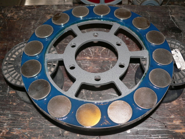
Normally for a 12 foot diameter 48 Volt alternator we have been winding the coils with 70 turns using 2 strands of AWG 16 wire in hand. usually there is a small gap between the coils, which is not ideal in my mind. This time we wound with 68 turns using two strands of AWG 15 wire in hand. These were a 'close' fit but a bit too fat. In the picture above you can see a coil, with the number 3 in the middle... and a line below that. That line is the outer path of the magnets and the edge of the hole in the coil (at the bottom) should meet that line... so the coil is too fat.
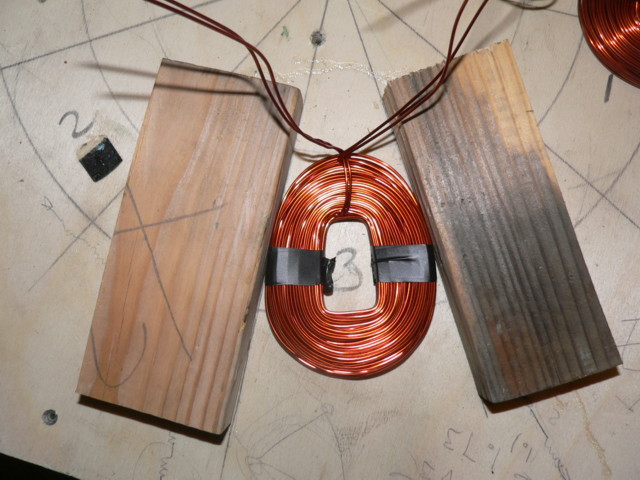
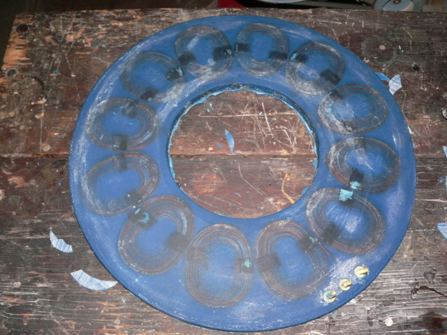
By actually gluing the two boards down to create a sort of 'from' - and pressing / 'whacking' the coils into the form, we got them to fit perfectly. Once we assembled this stator, the coils all fit perfectly in their place and they are touching one another on the sides. There is very little room to fit more copper in this machine.
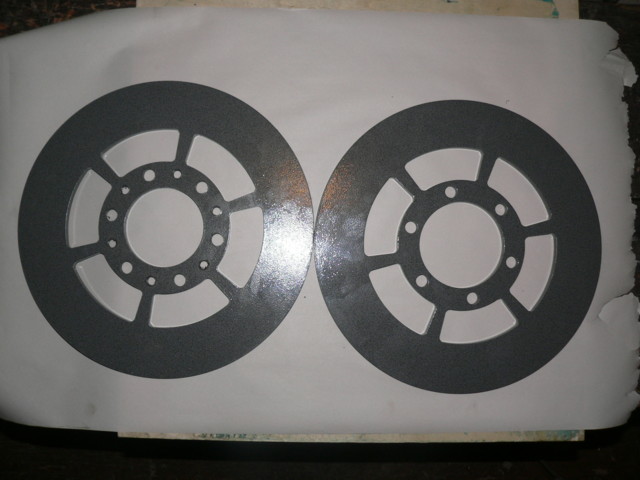
Pictured above are the powdercoated magnet rotors. They're water jet cut from 3/8 inch steel, they are 15 inches in diameter.
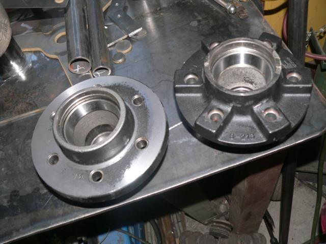
Pictured above are two different hubs that I ordered for this project. The one of the left is made in China, I get them from Southwest Wheel company. The one on the right is a Dexter hub which I can now get from etrailer.com. Until recently, etrailer did not offer such large hubs. This is a hub for a 6000 pound axle which fits a #42 spindle. Normally I use the one from SW wheel, but last time I got one (for Hughes workshop on Guemes Island) I noticed they stopped machining the back side of the hub. In the past, I relied on that surface to be machined so that we could fit a rotor on the back side, which I like to do in order to keep the alternator 'compact' and reduce the length of the hardware that supports the stator. (not a big deal really) Lately the back side is a raw casting. So, I turned it on the lathe to true it up and we used it. The Dexter hub from Etrailer would also work, but the back side is also not machined and the casting is much thicker.
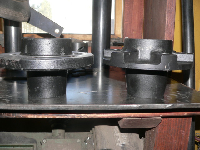
Another pic of the two hubs. Basically they are the same, but if one chooses to fit a rotor to the back side, the one on the left - from Southwest wheel, is still more practical, but a bit of lathe work is probably required to be sure the back rotor runs true.
Pictured above is the back magnet rotor, powder coated, with it's magnets on, stainless steel band and blue vinyl ester resin. One note about powdercoat and vinyl ester resin... if you ever accidently get a bit of resin on the front side of the rotor, it becomes clear that vinyl ester resin really sticks very well to the powder coat... which is good!
The stator is finished in the picture above... again, I added a bit of blue pigment to the resin for fun! The coils came in at 12.25 pounds, so the weight of a single phase (8 coils) is about 8.13 pounds. Going off a wire gauge charge, I figure the length of wire in one phase then to be about 411 feet, which should make the resistance of 1 phase about .66 ohm.
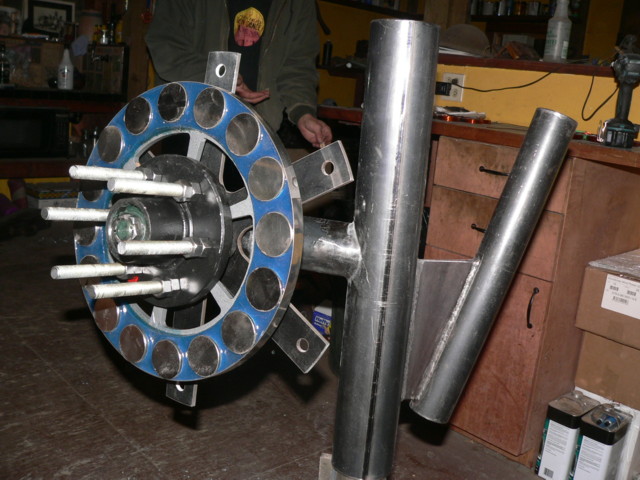
Pictured above the machine is coming together....
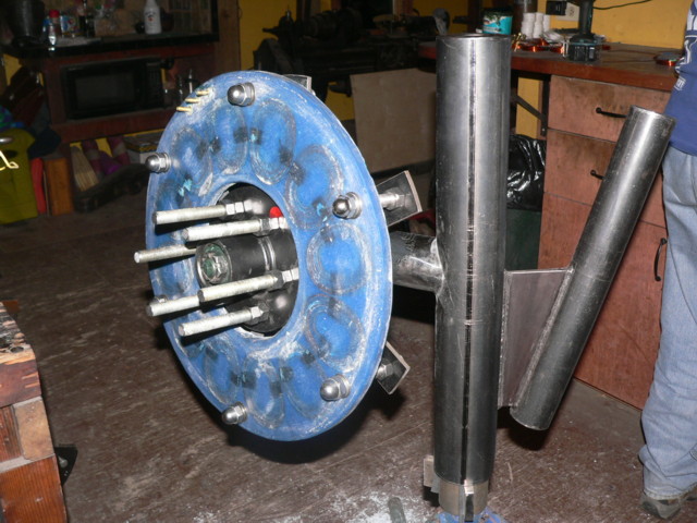
The stator is mounted to the stator bracket with 5/8 inch hardware.
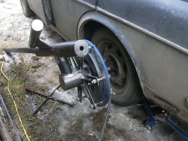
We tested the machine on the back of my car. Cutin speed (50 volts DC after the rectifier) is right at 125 rpm. The airgap is about exactly 15/16 inch. After running the machine between 1 and 1.5kW for about 1 hour the hottest spots I could find on the stator were up around 180 deg F, which is within reason I think.. and I expect it would be quite a lot cooler if it was up in the wind under such conditions.
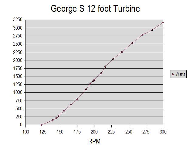
There is the power curve we measured while testing it on the volvo rear end. I also made a short video of the test on youtube which you can see here:
http://www.youtube.com/watch?v=1_DlgoTSEU8