Author Topic: Iron Genny  (Read 5959 times)

0 Members and 1 Guest are viewing this topic.

phil b

  • Sr. Member
  • ****
  • Posts: 304
  • Country: us
Iron Genny
« on: June 02, 2007, 05:09:30 PM »
It has some old and new ideas incorporated into it's unique design.


I'm not too good at 'splain' things, but here goes...


Double 12" rotors with 24 magnets each, 18 coils on each side of a magnet steel laminated stator. 8 foot prop.

I told you it was different!
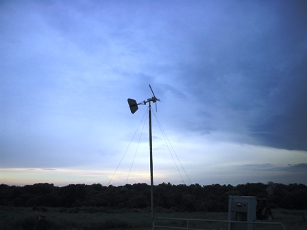


This unit was built in an attempt to accomplish several things:


  1. have fun!
  2. user adjustable furl
  3. deal with excessive heat in the stator
  4. 24 and 48 volt capabilities, maybe higher too
  5. seal the blades to keep moisture from entering and unbalancing them.
  6. have fun!


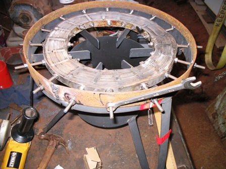
I started off with a piece of 3/4" steel laminate, wound just

like the stators were made on the old otherpower board. I used

the same mold as the rotor was cast in and wound the laminates

as tight as I could. Next, it was drenched in electrical

varnish and air dried. I quickly learned the magnets would

still warp the laminates. So,I drilled 18 holes around the

parameter and inserted 1/4" stainless steel allthread. 3/32"

steel hoops were added to secure the laminated firmly.  I also had to weld the laminates about 1/8" deep on each side using a 308 stainless steel rod. The 1/4" allthread was tightned evenly around the hoop with a torque wrench at 12 ft/lbs.


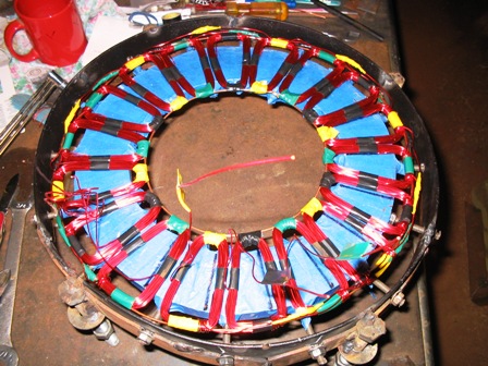
The coils came next. The laminates were covered in painter's tape to avoid any sharp edges coming in contact with the magnet wire. 30 winds each, #18 magnet wire, 18 coils on each side. The legs of each stator were taped together, then the stators were tied with string to keep them on the laminates and in the right place. Varnish was painted on the coils, string and connections. Smooth-on 300 plastic was painted on both stators to seal and 'glue' the coils on the lams. Both stators were wired seperately in star.  12 wires come out of the completed unit and are tied together at the terminal block. The box that houses the terminal block can be seen in the first pic, just behind the stator. Each stator produces about 30 volts when spun by hand. In the near future, MPPT may play a big role in this unit.


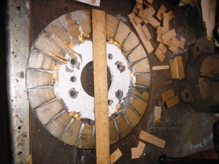
I used a 12" diameter piece of 1/2" steel for the rotors and mounted 24 magnets on each one. Magnets are the 3/32" thick magnets from Windstuff Ed. The edges of the magnets do touch at the edge of the rotor. I think it's probably causing some power

loss. All of this has it's trade-offs. I sealed the entire rotor in Smooth-on 300 and painted them.


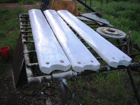
Blades are from my original unit. Water was entering the wood where the blades were bolted to the rotor. I drilled out the holes by an inch, poured the Smooth-on into the holes and redrilled them to 1/2". Maybe this will work.


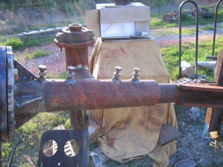
Here's the adjustable furl mechanism.

I've taken the compound hinge assembly and split it up into two angles. The first one that's attached to the yaw bearing pipe is welded in at 10 degrees. The second angle is adjustable to whatever you want. It's a pipe within a pipe, secured by

tightning 4 top bolts. If the bolts fail, the tail should drop and cause the genny to turn backwards and slow down. Out of balance blades should also cause tail drop.

Adjust the angle of the tail and tighten the 4 bolts on the top to control the furl. I used  DanB's method using a rope and fish scale to adjust the furl. It's set at 10 pounds.The generator bolts to the flange on the left.


Moch-up of unfinished generator
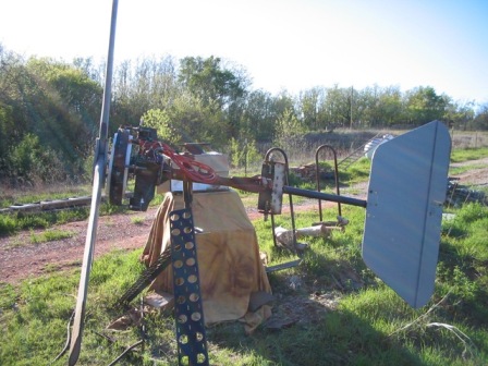


I've seen 60 volts going into the batteries and 70 Hz when configured for a 48 volts system. The Hz are high enough, it may get a transformer hooked to it, just for fun. As yet,I don't have good solid data on it's output. I plan to hook up my

datalogger to it soon!


Constructive comments are welcome!

« Last Edit: June 02, 2007, 05:09:30 PM by (unknown) »
Phil

tecker

  • SuperHero Member
  • ******
  • Posts: 2183
Re: Iron Genny
« Reply #1 on: June 02, 2007, 11:37:44 AM »
That came out nice I like the idea of mounting the coils on the steel .
« Last Edit: June 02, 2007, 11:37:44 AM by tecker »

Flux

  • Super Hero Member Plus
  • *******
  • Posts: 6275
Re: Iron Genny
« Reply #2 on: June 02, 2007, 11:41:13 AM »
It's different and you have certainly satisfied requirement 1.


I agree that you have too many magnets for the diameter.


I think you would have done better to have wound it as a torus but your method is easier.


Look forward to the results.


Flux

« Last Edit: June 02, 2007, 11:41:13 AM by Flux »

phil b

  • Sr. Member
  • ****
  • Posts: 304
  • Country: us
Re: Iron Genny
« Reply #3 on: June 02, 2007, 02:37:50 PM »
Flux,

I had full intentions of winding the stator as a torus when I started. I did one 20 wind coil and one 30 wind coil. They actually made higher voltages with less winds. A torus would have saved about 7 feet of wire per coil. The coils I settled for are 1/4" tall. Torus was half that. I could not figure out a good winding technique.  Lots of fun. I did want to get it finished though...so I could start on it's big brother. The stator will be 16" instead of 12", It should make torus windings easier.  
« Last Edit: June 02, 2007, 02:37:50 PM by phil b »
Phil

tecker

  • SuperHero Member
  • ******
  • Posts: 2183
Re: Iron Genny
« Reply #4 on: June 02, 2007, 02:57:00 PM »
I'm  working on a small torus Bailing wire core(soft steel) in sections the winds I slide over the end .I think very little flux escapes the core with the winding around the core .
« Last Edit: June 02, 2007, 02:57:00 PM by tecker »

hiker

  • Hero Member
  • *****
  • Posts: 1661
  • BIG DOG
Re: Iron Genny
« Reply #5 on: June 02, 2007, 03:45:11 PM »
cool..

always wanted to try a torus stator..[pulling all that wire throu the stator hole over and over again would take some time]

seems like you could load it up with a ton of coils side by side..

and woundnt the rotors have to repel each other instead of atracting??
« Last Edit: June 02, 2007, 03:45:11 PM by hiker »
WILD in ALASKA

phil b

  • Sr. Member
  • ****
  • Posts: 304
  • Country: us
Re: Iron Genny
« Reply #6 on: June 02, 2007, 03:45:53 PM »
OH OH Tecker,

You shouldn't say things like that! Another thing I'll have to try. Sorry, I need to start a chapter of Wind Generators Anonomous! I doubt I'll ever be cured, maybe someday only recovering. :)


If the flux lines in the baling wire prove to be of little effect, that would be perfect because the grooves would help keep the coils in place. The grooves wouldn't be deep enough to cause cogging. I have several thousand feet of new baling wire on hand.

« Last Edit: June 02, 2007, 03:45:53 PM by phil b »
Phil

hiker

  • Hero Member
  • *****
  • Posts: 1661
  • BIG DOG
Re: Iron Genny
« Reply #7 on: June 02, 2007, 03:49:23 PM »
(blank)
« Last Edit: June 02, 2007, 03:49:23 PM by hiker »
WILD in ALASKA

wdyasq

  • Hero Member
  • *****
  • Posts: 1324
Re: Iron Genny
« Reply #8 on: June 02, 2007, 04:03:49 PM »
Nice work Phil.


Glad to hear it is producing a high Hz for you.


Ron

« Last Edit: June 02, 2007, 04:03:49 PM by wdyasq »
"I like the Honey, but kill the bees"

phil b

  • Sr. Member
  • ****
  • Posts: 304
  • Country: us
Re: Iron Genny
« Reply #9 on: June 02, 2007, 04:06:30 PM »
I couldn't get my big fingers and the magnet wire around the laminations on this unit or it would have been a torus. 30 feet of #18 per coil. There's about 1 1/2" between the laminations and the hoops. I ruined my good used wire! :(


I can see the possibility of overlapping coils on a torus. Instead of 18 coils, why not 36? That was my original intention.


The 20 and 30 wind toriod test coils worked fine by using N-S on the opposing magnet rotors. By my test results, I don't think the flux fully penetrated the laminations. With larger magnets, I'll bet the story would be different.

« Last Edit: June 02, 2007, 04:06:30 PM by phil b »
Phil

tecker

  • SuperHero Member
  • ******
  • Posts: 2183
Re: Iron Genny
« Reply #10 on: June 02, 2007, 04:37:15 PM »
 Yeah with Two flat sections One cross cut per section the coils ( pre wound ) go thru the cuts and position  side by side . Rotate the flats a few degrees after they're done .  I have to work around some mounting holes I don't think It's going to effect it that much. It's taking me a a long time to finish ( work )
« Last Edit: June 02, 2007, 04:37:15 PM by tecker »

windstuffnow

  • Hero Member
  • *****
  • Posts: 1065
  • Country: 00
Re: Iron Genny
« Reply #11 on: June 02, 2007, 08:24:09 PM »
 Pretty slick there Phil!  If I wasn't so busy I might do some more experiments with the silicon steel.   I like the idea of a torus layout and may make the time to put a small one together for fun.  


 I'll have to check my stock but I'm pretty sure I do have an 80lb roll of the 3/4" M19 silicon.  I'll shoot you an email after I check the rolls and sizes...


Nice work!

.

« Last Edit: June 02, 2007, 08:24:09 PM by windstuffnow »
Windstuff Ed

Ungrounded Lightning Rod

  • SuperHero Member
  • ******
  • Posts: 2865
repulsive magnetization
« Reply #12 on: June 02, 2007, 11:25:16 PM »
always wanted to try a torus stator... woundnt the rotors have to repel each other instead of atracting??


With a pair of rotors intended to have the torus mounted between them the rotors should be positioned so they repell each other when the torus is not mounted between them.  But when the torus is in position they will attract the torus more than they repell each other so you still need to jack 'em down and support them against their attraction.


You also have to support the torus against the massive attraction of ONE rotor during assembly, and the midpoint position is the "top of the hill" energy-potential wise, so if the torus is a little off-center it will try to move farther off-center.  This makes the mechanical structure difficult to design and execute.


Another possibility is to use radial rather than axial flux, with a ring of outward-facing magnets inside the torus, a ring outside, or both (i.e. a cup of magnets with the torus supported inside it).  With the double ring the magnets will repell as you assemble the cup, then suck the torus in.  Again the torus will try to move more off-center if it's not dead-on concentric.  You might temporarily wrap it with a spacer to  keep it near-centered while jacking it in, then pull (or disolve) the spacer once it's in place and bolted down.  For this design the torus' core needs to be a "stack of washers" rather than a "coiled strip".

« Last Edit: June 02, 2007, 11:25:16 PM by Ungrounded Lightning Rod »

wooferhound

  • SuperHero Member
  • ******
  • Posts: 2288
  • Country: us
  • Huntsville Alabama U.S.A.
    • Woofer Hound Sound & Lighting Rentals
Re: Iron Genny
« Reply #13 on: June 03, 2007, 06:17:47 PM »
you said

"Double 12" rotors with 24 magnets each, 18 coils on each side of a magnet steel laminated stator."


I think you would get considerably more performance out of the machine if you took out the laminates from between your 2 magnet rotors and just left the coils in there. Laminates are used to reduce the cost of machines by letting you get by with only 1 magnet rotor and the laminates take the place of the second magnet rotor.

« Last Edit: June 03, 2007, 06:17:47 PM by wooferhound »