This project was started long ago and is finally finished.
The idea was to overcome some of the common problems when trying a small, cheap, and easy first windmill. And have a good chance of having it actually work!
Box fans seemed like a good place to start. My neighbor threw this one away.
The main problems for box fans are magnetic cogging and high coil resistance.
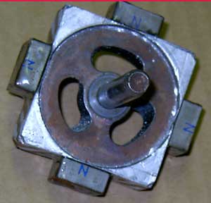
My "big new idea" is using only 4 magnets for the 6 coils. This almost totally eliminated the magnetic cogging common to 6 magnet armatures.
This also allows the coils to be seperated into 3 series pairs, and that reduces the coil resistance.
Tools required are very basic. I only used a pencil, hack saw, file, small vice, wire cutters, pliars, screw driver, razor blade, 1 hour epoxy, soldering iron and solder, hot glue gun and hot glue. I do not believe that hot glue is the best choice to insulate and hold wires in place, but I did not think this would work as well as it does.
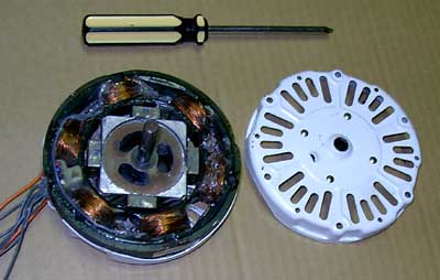
This motor is from a 20" box fan. The fan blade will surely turn it, but it will be fall before I can test it in the wind. Too many trees here.
The motor has bushings instead of bearings, and therefore will wear out sooner.
If there is a copper pin through the laminations, it should be removed.
This motor did not have one.
The name plate sticker reads 120V AC, 60HZ, 2.1A.
The magnets were placed on the end of the armature, marked a line with a pencil, cut with a hack saw, cleaned up with a file, then epoxied on the magnets N/S/N/S.
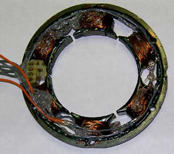
The stator had 4 wires in parallel wound from coil to coil in series.
These wires were cut allowing the wires from deep in the coils to be long.
The other end was carefully unwound from the outside of the coils so they were long enough to work with.
The insulation on all the ends was stripped about 1/8".
The meter set to ohms found ends of the same wire, so they could be reconnected properly.
Take care when soldering, so no solder drips onto the coils.
The soldering was time consuming and tiring. Don't expect to do it in an hour.
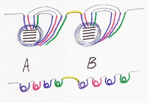
The sketch shows how I reconnected the wires of opposite coils. 1A to 1B. 2A to 2B. 3A to 3B. The outputs are AC, and need rectified to DC for battery charging.
That is covered in depth elsewhere on this board.
The wires were insulated and held in place with hot glue. Like I said, probably not a good idea.
If one pair of coils has a very low output, one coils ends should be switched.
Meaning the wire going to the other coil now becomes the output, and the former output now goes to the other coil.
Each reconnected coil coil is 9 ohms, each pair in series is 18 ohms.
Each coil in this conversion makes 0.45 amps into a 12V battery at 650 RPMs, 1.2 amps at 800 RPMs, and 0.75A at 1100 RPMs.
With all 3 coils operating at 1100 RPMs, that is 2.25 amps for about 30 watts output.
One pair of coils was faulty. This has reduced the total output, but has nothing to do with the construction. (3A and 3B are the faulty coils) Maybe that is why it was in the garbage, but it probably happened from so much handling for so long.
These magnets are most probably over powered for this project. 3/4 x 3/4 x 5/16" N45 grade neos. They just happened to be here and fit nicely, so I used them.
The whole thing.

Nothing to exact.

Not very pretty.

The wiring connections for one pair of coils.
The top shows how it looks aon the laminations.
The bottom shows how it would look if they were all seperated.

I hope this helps someone looking for something small for a first try.
Any and all comments welcome.
Thanks to everyone who very patiently helped me with this unusual conversion!
G-