Howdy out there in electron land,
The rule of thumb that I've seen a bunch of times on the board is that the hole in the coil should be about the same size as the magnet. Being the curious type, I wanted to see what happened to the waveform as I changed coil core size in relationship to the magnet size.
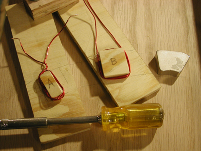
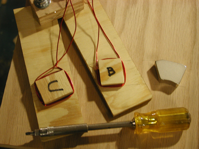
To generate the wave forms, I made three test coils. The hole in test coil A was half the width of the magnet. The hole for coil B was about the same size and test coil C had a hole 25% bigger than the magnet. The vertical legs of the coil (the effective part) all had three turns of 18 AWG magnet wire for all three coils.
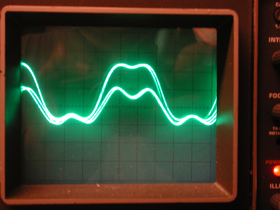
Since I have only a two channel o'scope, I first compared coil A to coil B, with the following results:
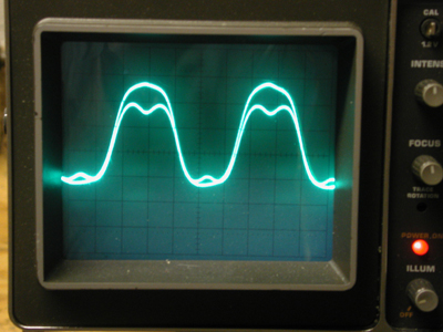
Then I compared coil B and coil C with the following results:
I have superimposed the two waveforms for easy comparison. In the A vs B pic, the very short AC wave with the pronounced dip in the middle is the output from coil A, the little skinny coil. It's obvious that you really start losing efficiency when the magnet can cover both legs of the coil at the same time, causing a voltage cancellation.
In the B vs C wave form comparison, C definitely outperformed B, with virtually no dip as the magnet passes over the center of the coil. This demonstrates that the flux doesn't just shoot straight out of the magnet, but rather, spreads out somewhat, so we still get a little voltage cancellation in coil B as the FLUX of the magnet can cover both legs at the same time, briefly.
Like everything though, it's a compromise. If you make really big holes in your coils, you'll have really great "efficiency" and pretty wave forms, but less total output than if you pack more copper in with a smaller hole size. However, this is definitely a case of diminishing returns. If you fill the air core hole up with wire completely, the very middle part of that will generate basically no useful electricity and just add to total resistance, reducing your generating capacity.
I intentionally used very few turns in the coils, to eliminate the averaging of the wave form from a full coil. A full solid coil with no central gap might still show a decent wave form as the outer layers are compensating for the cancellation of the very center.
So yeah, I'm back to making the holes in the coils just a little smaller than the magnet.
Voltage and amperage measurements with a Fluke DMM produced a similar outcome, with the small "A" coil producing about half of the watts of the the "B" coil, despite having the same amount of copper in the effective part of the legs.
Best Regards,
troy
