Author Topic: Led master class; pt 1 (theory)  (Read 15938 times)

0 Members and 1 Guest are viewing this topic.

commanda

  • Hero Member
  • *****
  • Posts: 731
Led master class; pt 1 (theory)
« on: April 20, 2007, 09:53:51 AM »
There's been a lot of discussion of late about led lighting. In particular about reliability (or the lack thereof).


In this thread

http://www.fieldlines.com/story/2007/4/15/205620/470


I started explaining why a single resistor is not very successful when the system is powered by lead-acid batteries.


To recap;


Led's are current operated devices. The voltage drop across them is nothing more than a practical nuisance. The ideal led would behave the same as an ideal zener diode. Below a certain voltage, they would draw no current. Above a certain voltage, they will draw as much current as the supply can deliver.


In your case, it only works because the leds are not perfect zeners, and the battery voltage just happens to be at one particular sweet spot. What happens when that battery is being charged, and the voltage is approaching 15 volts. What is your led current then?


And if resistors are bad and waste heat (energy), what do you think that red led is doing, especially if you cover it with black tape.


The correct way to power an led is with a constant current source, so that the current remains constant irrespective of battery voltage. A series resistor can approximate a constant current source over a limited range of input voltage, if the difference between battery voltage and combined led voltage is high enough.


Some worked examples;

R = E/I

E = Vbatt - Vled

I = 20mA

Vled = 3.6 volts

Vbatt = 11 to 15 volts


for one led, the resistor value at Vbatt = 11 volts is

(11 - 3.6) / 20mA = 370 ohms

when Vbatt is 15 volts, this resistor will give an led current of

(15 - 3.6) / 370 = 30.8mA


for two leds, the resistor value at Vbatt = 11 volts is

(11 - 7.2) / 20mA = 190 ohms

when Vbatt is 15 volts, this resistor will give an led current of

(15 - 7.2) / 190 = 41.1mA


You can see the trend. I leave it to the interested reader to calculate values using 3 leds.


So, to use a simple fixed resistor, we can see that the best we can do to achieve a semi constant current in the led is to use a string of one led per resistor. Not very efficient. And we still get a change of 50% in the led current between empty (20mA) and full (30.8mA).


And so we get to circuit 1.
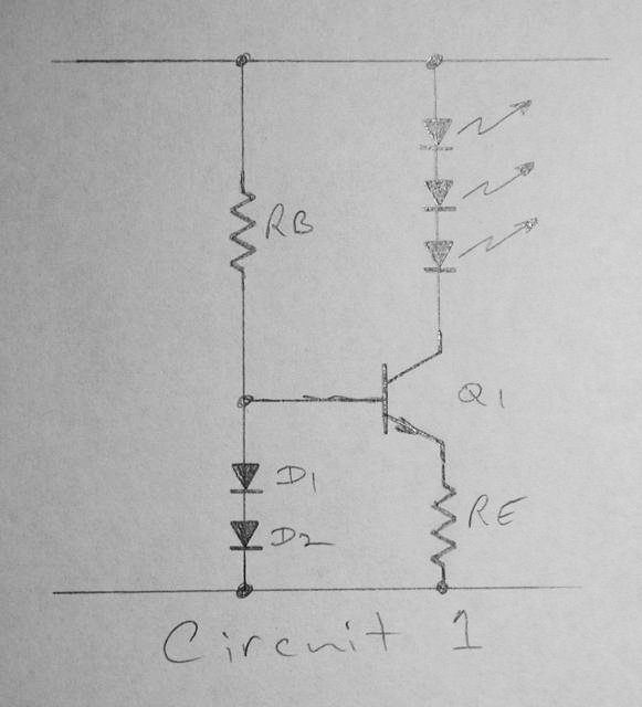


Simplifying and idealising, it works like this.

The 2 diodes drop a voltage of 1.2 volts. The transistor drops 0.6 volts across the base-emitter junction (Vbe), leaving 1.2 - 0.6 = 0.6 volts across Re. Since this voltage is obviously constant, and the resistor value is constant, the transistors emitter current (Ie) must also be constant. And since the transistors collector current (Ic) is equal to Ie, the current in the leds must also be constant.


In practice, the voltage across the 2 diodes will vary as a function of the supply voltage (google pn junction dynamic resistance if you must know more). Also, the Vbe of the transistor will vary as a function of heat. As the supply voltage goes up, the transistor drops more voltage across the collector emitter junction (Vce), hence power dissipation goes up (Vce x Ic) generating heat in the transistor. Vbe goes down as a function of temperature, approx 2mV per degree C. This can be partially mitigated by physically bonding the 2 diodes to the transistor, so the diode voltage also goes down as a function of temperature.


Expanding this circuit, we can run multiple led strings, adding just one transistor and one resistor for each additional string (see circuit 2).
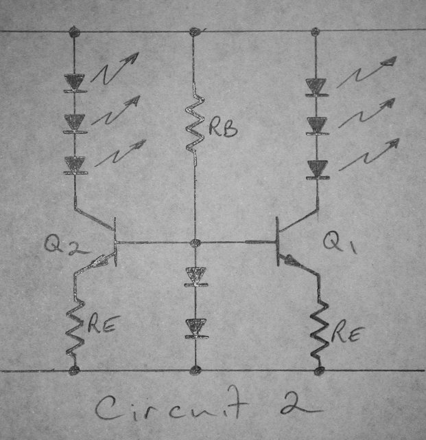


The problem here is you can't easily bond the transistors and diodes together to mitigate the thermal effects.


And so on to circuit 3.
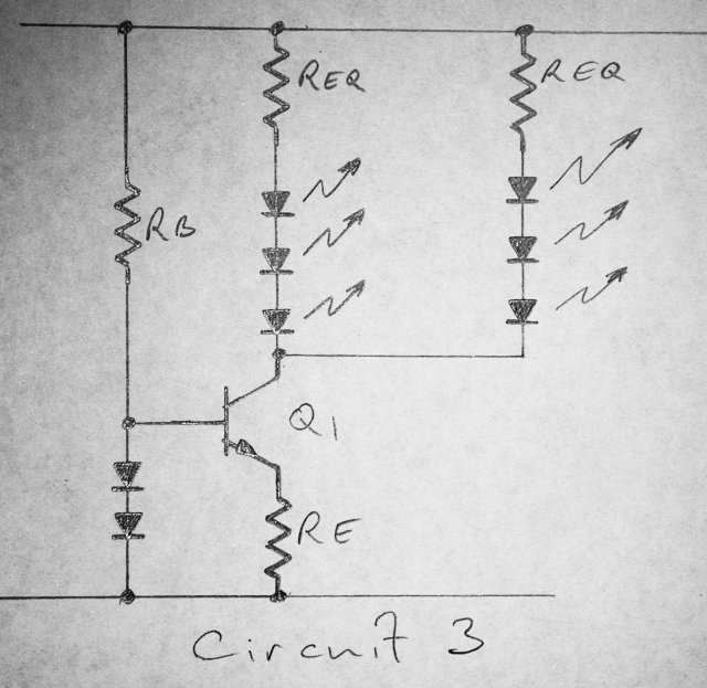


We use one transistor to deliver current to multiple led strings. We now need to add a small resistor in series with each string (Req) to equalise the leds, because they won't all have exactly the same forward voltage drop. Problem now is we have also multiplied the transistor self-heating effect, because it is passing n strings as much current.


And now to the piece-de-resistance.
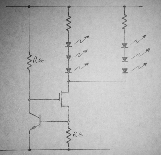


In circuit 4, we use a fet as a variable resistance element. Rg biases the fet on, current starts to flow in the fet, generating a voltage across Rs. As this voltage approaches 0.6 volts (Vbe of the transistor), the transistor starts to turn on. The transistor decreases the voltage on the gate of the fet, tending to turn it off. We now have a constant voltage across Rs (Vbe), and a constant drain current in the fet. Again, we run multiple strings of leds, each with their own little equalizing resistor (Req).


In practice, we now have the exact opposite of the previous example when it comes to heat. We bond the transistor to the fet. As the fet gets hot, the transistor Vbe decreases, so the voltage across Rs decreases, and the current through the fet decreases. We have now effectively prevented thermal runaway. There's a new concept for you, didn't mention that one before, did I?


Go back to the very first example, the simple led and series resistor. Now, instead of using an ideal led, lets use a real led. The forward voltage drop of a real led behaves exactly the same as the Vbe of the transistor, minus 2mV per degree C. What happens to the current through the led as the temperature rises? Vbatt minus Vled divided by the resistor. If Vled falls, then the current must increase, leading to more heat, therefore more current, very quickly terminal. If you have 3 leds in series with one resistor, the effect is multiplied 3 times.


Taking circuit 4 to its logical conclusion, you end up with this dimmable led circuit.

http://radiolocation.tripod.com/LEDdimmer/LEDlampDimmer.html


I have deliberately left out the switchmode variants of driving leds, so as to spare our readers the frustation of being presented with circuits too complex for any sane person to build, or IC's made of specially imported (from a galaxy far, far away) unobtainium, and/or obsoletium. This last one is copyright by me, Amanda Wynne, 2007; I just thought of that one.


In part 2 of this led master class, I will present some actual examples of these circuits, complete with component values and performance data. I bread-boarded circuit 4 today, and it is sweet. 3 red leds, 10mA at 8 volts, 11mA at 30 volts.


Till next week.


Amanda

« Last Edit: April 20, 2007, 09:53:51 AM by (unknown) »

dinges

  • Hero Member
  • *****
  • Posts: 1294
  • Country: nl
Re: Led master class; pt 1 (theory)
« Reply #1 on: April 20, 2007, 05:11:43 AM »
Muchos gracias! Good read. Saved for future reference & looking forward to lesson 2.


I have used circuit nr. 2 in the past as a current source; for this application (lighting LEDs) is it a big issue that the diodes and transistor are not physically bonded together? Keeping in mind that we are not striving for a highly accurate laboratory current source but just something to keep the current to the LEDs more or less constant, I wonder how much current could vary because of thermal differences in the diode and transistor.


Circuit nr. 2 seems the simplest to use, to me, but as I said, am curious as to how much the thermal effects cause current to vary.


Do you have some design equations too, or are you keeping us in suspense till lesson 2 ?

« Last Edit: April 20, 2007, 05:11:43 AM by dinges »
“Research is what I'm doing when I don't know what I'm doing.” (W. von Braun)

disaray1

  • Full Member
  • ***
  • Posts: 196
Re: Led master class; pt 1 (theory)
« Reply #2 on: April 20, 2007, 05:53:21 AM »
 Thanks Amanda! Very well explained. I think the Ebay LED's I bought (Edison base,16 led spots, made in China) all died fast from voltage variance and "thermal runaway", as you explained. Just need to dissect them and post-mortem.


 Cell phones have parts made of "obsoletium", don't they?


 Happy Friday!  David

« Last Edit: April 20, 2007, 05:53:21 AM by disaray1 »

CompDoc

  • Newbie
  • *
  • Posts: 8
Re: Led master class; pt 1 (theory)
« Reply #3 on: April 20, 2007, 06:06:15 AM »
Very well explained, Amanda.  How's the weather in Ausie?
« Last Edit: April 20, 2007, 06:06:15 AM by CompDoc »

RogerAS

  • Sr. Member
  • ****
  • Posts: 329
Re: Led master class; pt 1 (theory)
« Reply #4 on: April 20, 2007, 07:36:54 AM »
Amanda,


Wouldn't it be much easier to implement a 78XX series solid state volatage regulator or perhaps an LM317 adjustable regulator than this diode transistor setup?


I ask in ignorance, not arrogance.

« Last Edit: April 20, 2007, 07:36:54 AM by RogerAS »

BigBreaker

  • Sr. Member
  • ****
  • Posts: 302
Re: Led master class; pt 1 (theory)
« Reply #5 on: April 20, 2007, 07:49:09 AM »
That would only solve the voltage variability problem.  You'd still need to turn a stable voltage source into a current source.  The easy ways of doing that (IE with a resistor) are inefficient.  Amanda's circuit is quite slick.


Also style points for using discrete parts.  One IC solutions require you to find that exact IC.  Amanadas circuit could be made from a multitude of parts, with minor tweaks here and there.


Not everyone wants to place an order to Digi-Key for every little project.  Most people here take pride in scrounging.

« Last Edit: April 20, 2007, 07:49:09 AM by BigBreaker »

ghurd

  • Super Hero Member Plus
  • *******
  • Posts: 8059
Re: Led master class; pt 1 (theory)
« Reply #6 on: April 20, 2007, 07:55:34 AM »
Most excellent!

G-
« Last Edit: April 20, 2007, 07:55:34 AM by ghurd »
www.ghurd.info<<<-----Information on my Controller

commanda

  • Hero Member
  • *****
  • Posts: 731
Re: Led master class; pt 1 (theory)
« Reply #7 on: April 20, 2007, 07:58:17 AM »
Peter,


Like most things, the correct answer to your question is "it depends".


Like how many leds, how much current, what transistor (a TO220 case in free air is naturally going to not heat up as much as a TO92 in a tiny sealed case), what diodes (1N914's are terrible).


Amanda

« Last Edit: April 20, 2007, 07:58:17 AM by commanda »

commanda

  • Hero Member
  • *****
  • Posts: 731
Re: Led master class; pt 1 (theory)
« Reply #8 on: April 20, 2007, 08:07:26 AM »
Ahhh.........


BigBreaker comprehends the finer points of unobtainium and obsoletium. Go to the head of the class.


Amanda

« Last Edit: April 20, 2007, 08:07:26 AM by commanda »

commanda

  • Hero Member
  • *****
  • Posts: 731
Re: Led master class; pt 1 (theory)
« Reply #9 on: April 20, 2007, 08:11:55 AM »
How's the weather in Ausie?


Our Prime Minister, Little Johnny Howard, today proclaimed that we should all pray for rain.


Nice to see leadership in action, isn't it?


Amanda

« Last Edit: April 20, 2007, 08:11:55 AM by commanda »

commanda

  • Hero Member
  • *****
  • Posts: 731
Re: Led master class; pt 1 (theory)
« Reply #10 on: April 20, 2007, 08:32:19 AM »
Depends.


As BigBreaker pointed out, you still need a series resistor to turn that constant voltage into a constant current. 3 terminal regulators also require bypass capacitors on the input and output to guarantee stability. On a 24 volt system, the charge voltage can exceed 30 volts, most 3 terminal regulators go bang if you exceed 35 volts input, not much headroom there. And forget a 48 volt system.


Also, the TO220 case devices typically have a bias current of 20mA. Thats 20mA not going into your leds. And unless you go for the low-dropout versions, they need at least 1.2 volts between input and output.


The LM317 can be made into a constant current source with just one resistor, but again you have minimum input to output voltage differentials.


And none of these have the negative thermal characteristics of circuit 4 that I presented.


Amanda

« Last Edit: April 20, 2007, 08:32:19 AM by commanda »

americanreman

  • Newbie
  • *
  • Posts: 29
Re: Led master class; pt 1 (theory)
« Reply #11 on: April 20, 2007, 09:08:07 AM »
Good read, thanks for that...


Another approach worth exploring because of the low voltage requirements of led's and something I was doing on my boat to drive led's is using nicd batteries to control the voltage, nicd's hold almost constant voltage until they are fully discharged.


2.4 - 3.6 volt packs can be charged quickly or slowly from a bank of 12 volt deep cycles or efficiently over the course of the day with 1 or more small solar cells which can be placed near each battery pack. Follow the rules when sizing banks, always fully discharge before recharge and nicds can be cycled for years on a daily basis, I was going on 3 years with my setup. You can size the bank to run down at 2 am or whatever time you don't want light anymore, the next morning sun hits the solar cell, turns off the light circuit completely and then recharges for the next night.


This was for pathway, hallway lighting and backlit moldings around the ceiling of each cabin, I would leave them on all night, they were dim in the morning and ready for recharge from the next days sun.


A simple op-amp circuit could compare voltage cutting off charge at .2 volts above cell voltage, many schematics around for simple nicd chargers from a cigarette lighter and cheap prebuilt units too.


Also trickle charging the bank continuously at a C rate that won't kill the batteries (which small solar cells will do), and or disconnect charging when the light is in use easily through the use of a few transistors.


Do a google for the guy who disected the malibu circuit for solar garden lights and you'll breed some ideas from that (on at dusk, off at dawn and charging). You don't need a major circuit or ivy league solution to effectively use led's, just a little forethought.


In short, size solar to fully recharge the bank within the hours of day light you have without overcharging in relation to a bank size that provides the number of hours you need light for every night = no major circuit needed for charge control and full discharge of the bank before the next days charging cycle.

« Last Edit: April 20, 2007, 09:08:07 AM by americanreman »

RogerAS

  • Sr. Member
  • ****
  • Posts: 329
OK
« Reply #12 on: April 20, 2007, 10:12:42 AM »
BB,


Slamming Amanda's work was not my intent, but rather pointing out another option that is easier to understand and build, for me. Resistors could be eliminated entirely with a constant voltage source as I suggest.


Now for higher voltage systems (>12V DC) I must question the need to used LEDs at all. CFLs are vastly less power hungry, provide more lumens per watt and can be run from DC sources. Termperature compensation isn't required. Aside from semi-truck trailers and automotive aplications LEDs would be my last choice for lighting, even after oil lamps.


The 78XX series are easy to salvage from tossed equipment, I have a whole array of bins full of 'em, all got for free (wih heatsinks and all sorts of other goodies). I do take great pride in this scrounging myself. No Digikey or Mouser involved. Computer power supplies are full of good parts. Discete parts? LM series devices are everywhere and I doubt they will become obsolete any time soon! I haven't ordered a single thing from a parts supplier since '00. I've been a contributing poster to this forum long enough ('02) to accutely understand the concept of scrounging. Unlike some people that post here I actually live this stuff, and have used up my weight in solder tinkering with electronics. I claim no breakthrough devices or educated insight that places me in a superior position to anyone else. In that same vien I do not consider myself a lesser person for having learned in the school of hard knocks.


If I didn't have thick skin I think the tone of your message could be taken as offensive. I do know what works and since I'm no where near the head of the class I'll have to accept that my preceptions of reality vary greatly from what others experience.

« Last Edit: April 20, 2007, 10:12:42 AM by RogerAS »

richhagen

  • Hero Member
  • *****
  • Posts: 1597
  • Country: us
Re: Led master class; pt 1 (theory)
« Reply #13 on: April 20, 2007, 05:17:58 PM »
Nice work.  I will look forward to part two.  


I had read that your Prime Minister had asked people to pray for rain related to the use of water for agricultural irrigation, and that if it did not rain soon, that irrigation would be banned.  I wondered what contingency plans he was making to DO SOMETHING about it besides restricting the use of what water remains.  I had the opportunity to visit BT's parents ranch out in the drought effected area and it seemed bone dry to me.  I wonder how the farmers and ranchers are going to make it through this crisis. Rich

« Last Edit: April 20, 2007, 05:17:58 PM by richhagen »
A Joule saved is a Joule made!

BigBreaker

  • Sr. Member
  • ****
  • Posts: 302
Re: OK
« Reply #14 on: April 21, 2007, 02:41:16 PM »
I agree that 78XX are easy to find and I'm not slamming.  If I had one I'd use it too.


This being a DIY site, a lot of people find it fun to solve problems with a fewest part count and the simplest parts.  It's like programmers finding the most compact code to perform a common task.


Amanda took a typical DIY project - powering LEDs - and walked us through a nifty solution using a small number of simple parts.  The simplicity and effectiveness is the critical element, not that it works.  She also did a great job of explaining the EE of it all.


Again, I'm not slamming.  I thought you missed the point a bit by suggesting the 78XXs, but I'm biased.  To me voltage regulators are like Op Amps... big circuits hidden in tiny packages (most op amps have 90+ transistors in them FYI).  I studied EE and was more interested in the inspiration of the circuit than the result - arbitrarily lighting LEDs.


PS My EE kung fo is pretty lousy now.

« Last Edit: April 21, 2007, 02:41:16 PM by BigBreaker »

BT Humble

  • Sr. Member
  • ****
  • Posts: 475
Re: Led master class; pt 1 (theory)
« Reply #15 on: April 22, 2007, 05:31:41 PM »


Our Prime Minister, Little Johnny Howard, today proclaimed that we should all pray for rain.


Nice to see leadership in action, isn't it?


We're supposed to show respect Amanda, that's "The Right Honorable Little Johnny Howard". ;-)


Are you coming to the Unaugural on May 5?  I got approval for the bonfire from the bush fire brigade yesterday, and did a lot of mowing around the site.


BTH

« Last Edit: April 22, 2007, 05:31:41 PM by BT Humble »

finnsawyer

  • Hero Member
  • *****
  • Posts: 1565
Re: Led master class; pt 1 (theory)
« Reply #16 on: April 23, 2007, 09:06:18 AM »
O.K., so take an 8.2 volt Zener and put it in series with a 12 volt battery using the proper size resistor.  Off the zener, which maintains a constant voltage run as many resistor in series with led circuits as feasible.  Not particularly efficient but cheap, and the battery voltage can be run through its normal charge - discharge range as usual.
« Last Edit: April 23, 2007, 09:06:18 AM by finnsawyer »

BigBreaker

  • Sr. Member
  • ****
  • Posts: 302
Re: Led master class; pt 1 (theory)
« Reply #17 on: May 01, 2007, 09:45:17 AM »
Amanda - any thought to adapting this circuit for a wind turbine driven battery charging?


We can think about the battery as a current sink.  While the voltage across a battery only changes a little, the output voltage of a wind turbine changes a lot.  The driver circuit raises "ground" for the battery so that the difference between the turbine voltage and the "top" of the driver is 13ish volts - always - because the current is limited to acceptable level.


The "direct connect" method of charging a battery from the rectifiers of a wind turbine tends to stall the machine as the current rises too fast.  The voltage difference between the turbine to ground and the battery to ground is too high.  Current is determined by the resistance in the line and the change in voltage from the turbine to the battery.


Putting your circuit between the battery and the turbine would hold down the current at lower RPM and allow the rotor to speed up.  The next step would be to use the dimmer version to modulate the current according to turbine RPM, MPPT-lite.


A "cut off" is needed for when the battery voltage rises above the ref level and push the current into some heaters.  You wouldn't want the mill to freespin in open circuit.

« Last Edit: May 01, 2007, 09:45:17 AM by BigBreaker »