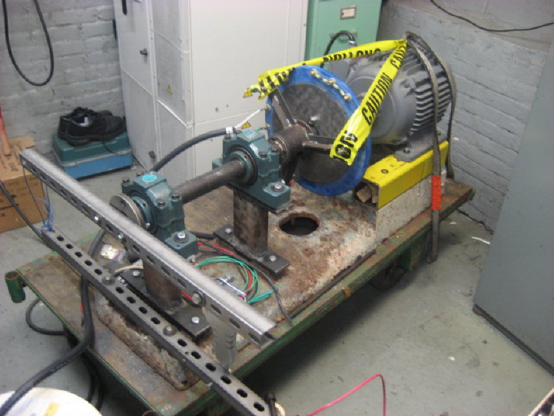
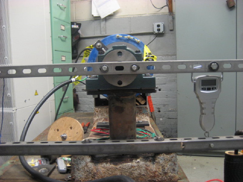
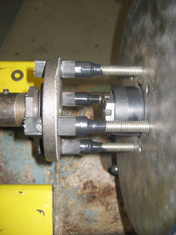
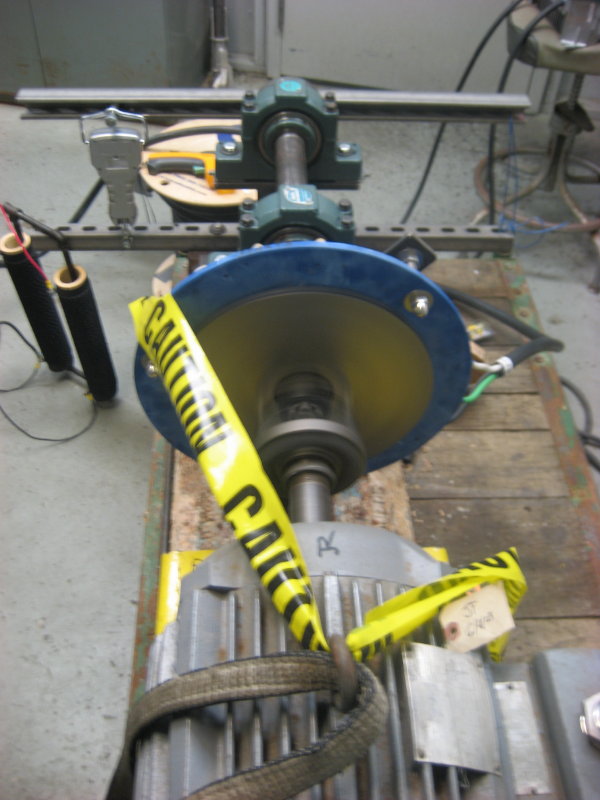
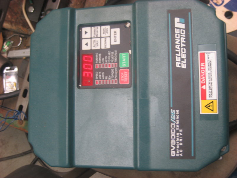
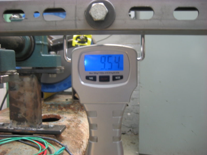
With some technical advice from some guys at work I fabricated a testing platform to gather data. I'm fortunate to have resources to borrow. The alternator test bed consists of a low rpm, 3 hp, 3 ph motor powered through a VFD controller. The power input is measured using a scale mounted 12" across a lever arm. To eliminate any trig math and angle measurements, the lever arm is on the rotational force center line and the scale is perpendicular to the lever arm.
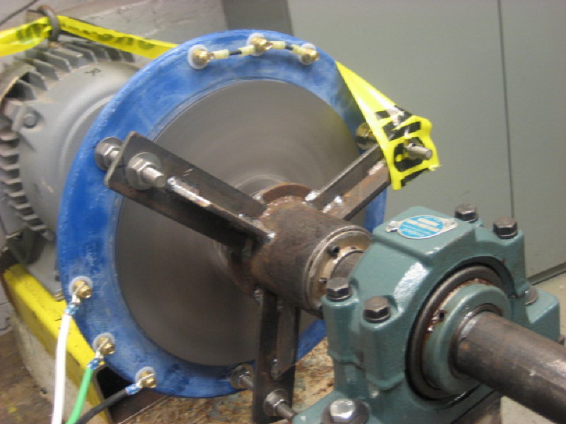
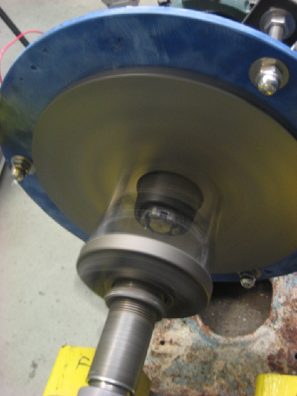
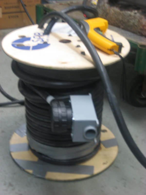
To reproduce actual conditions, the stator is wired with 120' of 6 AWG between the rectifier blocks. The plug is at 80', which will correspond with the base of the tower.
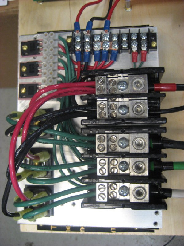
The rectifier and terminal blocks are mounted on a heat sink acquired at Forcefield. There are two sets of rectifiers, main and boost.
The DC-DC converter is "off the shelf" from Zahn Electronics. In trying to make it work for a wind turbine application, first I replaced the 0-100% pwm driver chip with 0 to 50% maximum pwm chip. There is a turn pot on the PCB for output boost voltage set point. This allows for boost cut-in speed adjustment (since the pwm is 50% max) and how quickly the output watts increase while boosting. With the boost voltage set all the up it will easily increase the output to 200 watts at 180 rpm. Decrease the boost set point below the battery voltage and wattage output does not occur until the alternator achieves battery voltage.
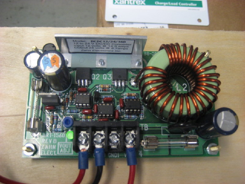
I have more investigation to do on how this boost converter will work. My concerns are that boost wattage output in going to change considerable as battery voltage change. (It controls to a voltage output.) For example, if I set the converter to load match the boost properly at 26v (float) and the batteries drop to 24v (LVL), is the wattage output of the boost going increase too much and cause a slow speed stall. Also I'm currently studying/playing with a microcontroller, may have to "hack" control of that turn pot voltage and try my hand at mppt; Or maybe place a mosfet on the boost converter output to take control that way.
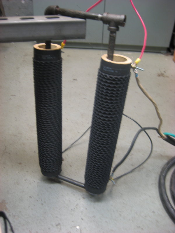
Two one ohm 1000 watt resistors in parallel are used for a dump load. At 30 volts these should be able to handle 60 amps wired parallel. Zantrex C60 is the diversion controller. The controller is a little oversized, but I have dreams of a larger turbine in the future, now control portion will be ready.
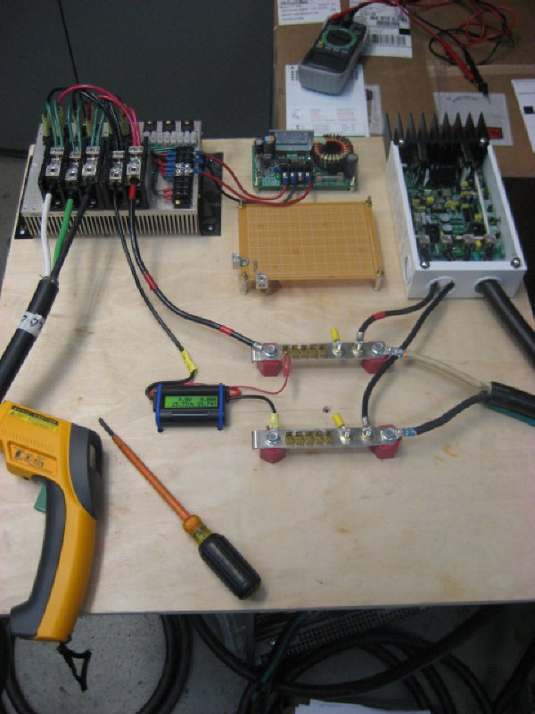
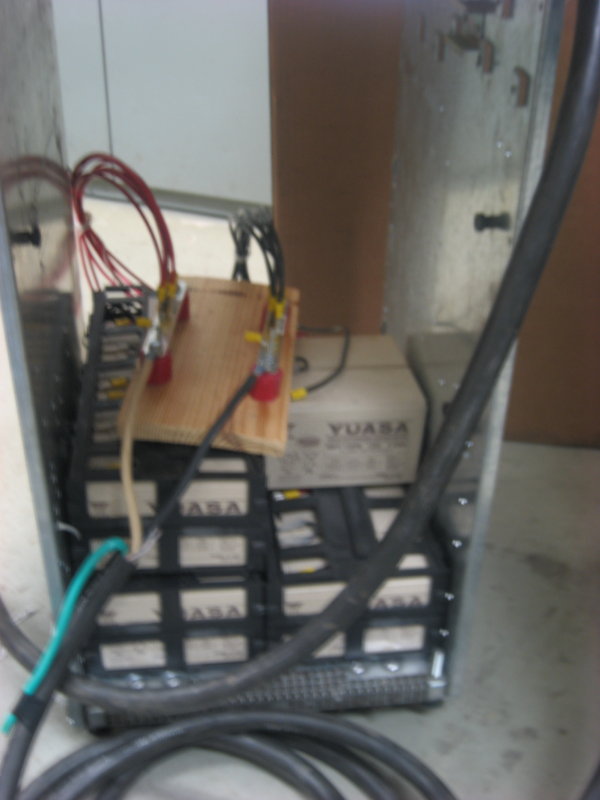
I was able to obtain an obsolete UPS. It was used as a power backup on a DCS. What a treasure trove of parts. The buss bars, standoffs, batteries, and nice flexible 6 awg wire are some of the parts put to immediate use. Also there is a beautiful heat sink (about 25% larger then one in the photo), rectifiers, and circuit breakers are some of the other useful parts.
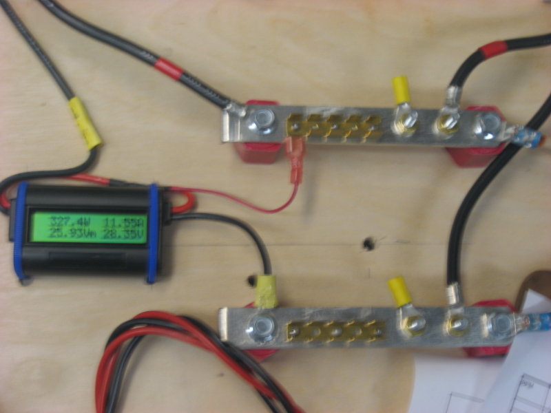
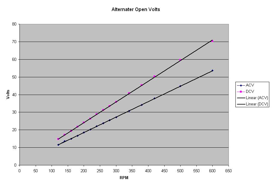
Here are some initial test results. I used a meter labeled true rms to measure acv. Below are the open voltage characteristics of the alternator
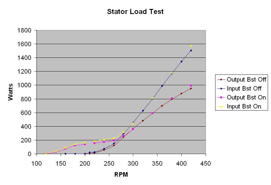
Now with the alternator loaded. The graph is a little busy since I also superimposed the boost while on and off on the same page. I plan on doing another series of tests with the boost not set as aggressive. The alternator efficiencies, at first look, seem to be too good to be true. This first round of test was completed in a short time and the stator had not heated up that much. Later, I ran the alternator continuously at 380 rpm. Initially, the output was 810 watts with a stator temperature of 120 F. After 15 minutes, the output dropped to 720 watts and the stator temperature increased to 180 F.
Ok, I'm doing all this because it is fun and to learn. But also, so I can build a rotor properly matched to the alternator. As of now, I'm thinking of carving a 2.6 meter diameter rotor designed for a 6.0 TSR. Please let me know if this is reasonable for the information collected thus far, or of some other data to collect. All comments welcome concerning this project.
Thanks
Boondocker