Author Topic: Trying a small handmade RACA  (Read 2973 times)

0 Members and 1 Guest are viewing this topic.

alancorey

  • Full Member
  • ***
  • Posts: 129
Trying a small handmade RACA
« on: December 06, 2006, 10:40:43 PM »
I got fed up with trying to use stepper motors and small DC motors then needing to put doublers and triplers on them to get the voltage up.  So I decided to make my own alternator.  I mean, people do it all the time, right?  I didn't know that the RACA was considered somewhat experimental.


I don't have access to a machine shop lately, so the only power tool used was the drill at the left side of the first picture.  Ok, I didn't saw the wood by hand, but I could have.  I wanted to use commonly available materials, perferably free.  I've taken several physics courses, but never paid much attention to the magnetism parts.


OK, so this is my first alternator, with 1 test coil.


RACA1 together


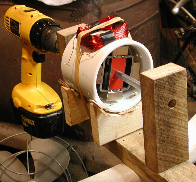
The base and the bearing supports are 1 x 2 inch oak.  The shaft is 3/8" cold rolled steel from a local Aubuchon store which I chucked in the drill and cleaned up with a file and emery paper to get the bearings on.  The bearings are from American Science and Surplus at $2.50/pair.  The body of the rotor is 2 inch square tubing which came from the dump as part of some exercise equipment.  The red pieces supporting the square tubing are 1/4 inch steel, also from the dump.  The white cylinder around the whole thing is a 3 inch PVC drain pipe coupling from the local Home Depot.  The cradle pieces under it are cut from spruce furring strip, also from Home Depot.  The fan blade mounts where the drill is.


The magnets here are 2 x 1 x 1/2 inch Neo, I forget what grade.  The coil is 150 turns of #22 wire wound on a 1.5 x 2 inch form.  There are holes in the pipe that I drilled on lines 30 degrees apart.  My original plan was to use 12 coils, and I was going to hitch the coils on with nylon monofilament by running it through the holes. Now the holes are mostly useful for measuring since they're 30 degrees or about 1 inch apart.


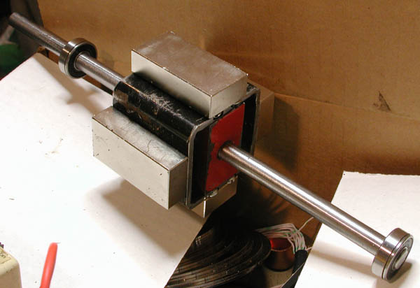
This is the rotor, shaft and bearings unmounted.
bare rotor


This is one of my high-tech bearing mounts:


wooden bearing mount


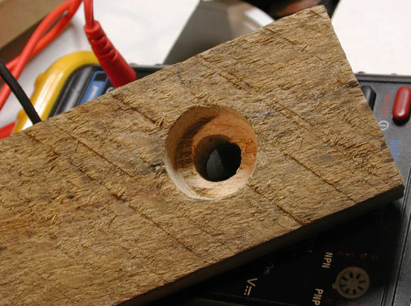
The only tool I bought for this was a 7/8 hole saw to fit the bearings.  I drilled holes into the oak to a saw depth of about 1/2 inch, letting the pilot drill go on through.  Then I turned it over and drilled out the pilot holes to about 7/16 to let the shaft stick through.  Then I turned it back over and used a narrow wood chisel to clean out the last of the wood in the hole and leave a fairly flat bottom.  


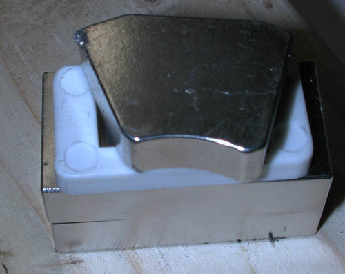
This is a shot of mostly the rotor:


rotor closeup


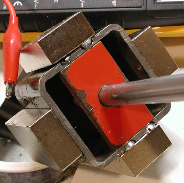
This makes the flaws easier to see.  I didn't build this for such big magnets, I only added them later to try to get more voltage.  The chunk of square tubing is 2 inches long and so are the magnets.  I had to replace my round head screws with flat heads and try to countersink them.  The holes are only about 1/8 inch from the ends, so trying to countersink them (with a drill bit) chewed out steel on the ends but didn't get the heads in far enough.  Here you can see that the upper magnet is held away from the square tubing by the screw heads.  This also makes the centering within the plastic tubing more critical, which is why it has shims under it and the brass screws holding it are loose.  It fit fine with the original magnets, but starting hitting on the top with the bigger ones.  The big ones also cover up my setscrew holes.  The alligator clip just wanted to be near the magnet.


This is one of the original magnets, a Neo from a big hard drive sitting on top of a pair of the current ones.
Magnet comparison

Using these bigger ones increased the voltage almost 20%, but I don't think it was worth it.


This is an idea for the next one, if I build another this way.  I'm trying to find existing things that might give good balance.  I want to build an alternator of some sort for a small hydro runner that turns at 2000 - 3000 RPM.


magnets on hex


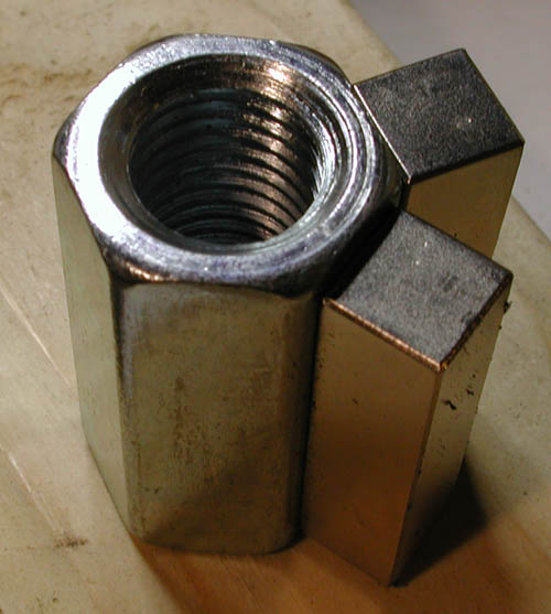
This is a couple of 1/2 x 1/2 x 2 Neos on a coupling nut for 3/4 inch rod that I found at Home Depot for about $1.30.  I've got some stuff that I think I can mount these onto a shaft with.  Yes, I've actually got 6 of the magnets.


I'm fairly new to taking pictures of a scope screen, but even so I've taken better ones than these.
big coil waveform


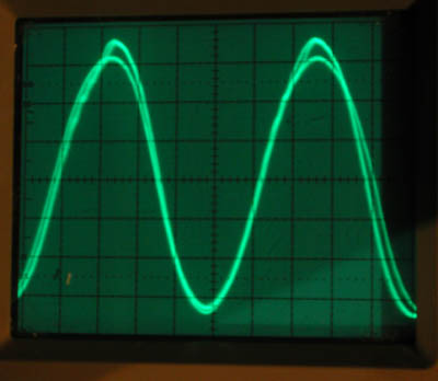
This was taken with the coil shown at about 500 RPM.  The scale is 0.5 volts per division.  A wide coil like this gives me a reasonable sine wave.  The camera exposure time was long enough for a few scope sweeps, so here they're stacked up on each other.  I don't know if the difference in the positive peak heights is real or not, or what would have caused it.  Looks like about 3.2 volts peak-peak or about 3.2/2.8 = 1.1 volts RMS.  Meter said 1.1, I think.


This is with a narrower coil.


narrow coil waveform


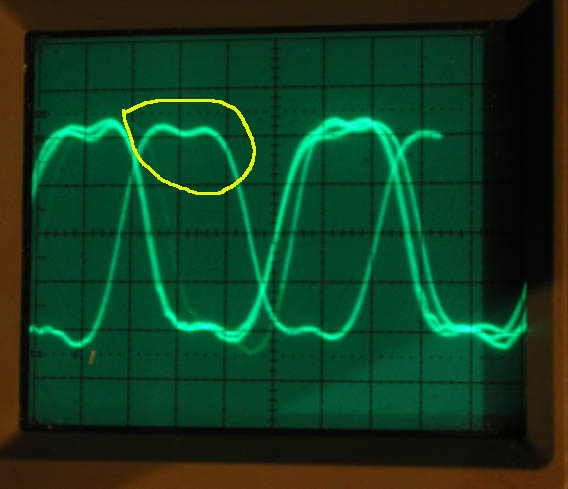
The picture's almost useless because of trigger jitter in the scope moving the traces around.  It was cold out there and getting late so I didn't try for a better picture.  If you look at the waveform top circled in yellow though, you'll see an odd double peak effect.  My first coil was only a little bit wider than one of the hard drive magnets, and this effect was even more pronounced.  This coil is about 1 inch or 30 degrees wide.  When I got up to 2 inches or 60 degrees this double peaking went away.  This is not the same vertical scale as above, and this coil is only about 18 turns.  The scope has a focus problem, and so does the camera.


I had expected to use coils a little wider than the magnets, but I guess because there are only 4 magnets the flux spreads out and I need wider ones.  I was hoping to fit 12 around the pipe and put 4 in series in each phase.  Now I'm not sure what I'll do.  The coil above is getting too thick to stack and make overlapping ones, at least it probably is.  I've got a spool of #26 wire ordered which should make thinner coils, but even twice as many turns isn't going to give me enough voltage.  And yes, I have the magnets N-S-N-S facing out.


I'm trying to get about 18 volts out of this to charge a 12 volt battery with a couple hundred feet of wire and a PB137ACV regulator which has a 1.5 volt dropout voltage.  So I'm figuring like 18/1.73 = 10.4 (RMS?) divided by however many coils I put in series.  I'm not even close.  On a windy day with my 20 inch fan blade on, I was getting 1.5 volts RMS on a good gust.  I'm getting a little over 200 MA short circuit current, I think. My meter's being strange and I have to read it on the 200 MA scale, which is getting maxed out about when the drill trigger is getting maxed out at 500 RPM.  


Looking at possible problems, there is some flux leakage into the square tubing.  Last time I checked (with the smaller magnets on) I could feel a little attraction inside the box with a screwdriver.  There's probably a little more with the bigger magnets.  Air gap: yes, air and plastic combined amounts to at least 3/8 inch in places.  This coupling has a sidewall about 1/4 inch thick, and it's also got a ridge inside for the pipes you're joining to butt up against.  I could try to cut or file it off, but then I'd need shims under the magnets to take advantage of the change.  With the original magnets I probably could have used a piece of 3 inch pipe to get a better fit, I just didn't want to buy a 10 foot piece to get 4 or 5 inches.  The coupling is a little bigger diameter, but cheap.


So since I'm waiting for wire anyway and I just found Ghurd's neat box fan conversion for a motor that looks a lot like one I've got, that's probably where I'm going next.  Maybe I can use my hard drive magnets in that.  Back to motors that someone else made.  I'll probably get back to the hydro about February and have to dig through 3 feet of snow to find my penstock.


  Alan

« Last Edit: December 06, 2006, 10:40:43 PM by (unknown) »

kitno455

  • Sr. Member
  • ****
  • Posts: 442
Re: Trying a small handmade RACA
« Reply #1 on: December 06, 2006, 06:11:11 PM »
i'm no expert, but i have played with a quite a few smaller gens/mags/coils on my scope. the double peak is caused by the coil being 'short' in the radial direction, such that two adjacent mags are not under their respective coil legs at the same time.


unfortunately, your coil is already too big in that direction because of the excessive gap between your poles. you really need 6 or 8 sided tubing to make this work. all that copper on the end windings is just resistance, esp. with such thin wire.


also- not having a flux return path is really, really hurting you. if you could wrap the outside of your drum in iron wire, or even better, a steel drum spinning along with the rotor, you would gain some improvement, esp. if you can get the airgap smaller.


it has been easier for me to build a motor conversion than a radial from scratch with my limited shop tools, axial comes in close second.


allan

« Last Edit: December 06, 2006, 06:11:11 PM by kitno455 »

WXYZCIENCE

  • Sr. Member
  • ****
  • Posts: 355
Re: Trying a small handmade RACA
« Reply #2 on: December 06, 2006, 07:48:50 PM »
Alan, I found on my RACA that the air gap is the most critical for good power output. I enjoyed reading your post and the pictures are excellent. We have the same problem here, three feet of the white stuff, drifts covering the cars. No use digging, no place to put it. Have a great day.
Joseph.
« Last Edit: December 06, 2006, 07:48:50 PM by WXYZCIENCE »

Stonebrain

  • Sr. Member
  • ****
  • Posts: 342
Re: Trying a small handmade RACA
« Reply #3 on: December 07, 2006, 06:08:55 AM »
Hi Alan,


I enjoyed your posting,lots of good quality pics.

You're doing good work.

I think you're on the right track with the racadesign.


I feel closer to your technological level than that of

wxyz,interesting that oscilloscopethingy.Is the higher

peak not from the magnet that's lift up a bit by the screw

(smaller airgap)?


I'm doing some experioences about the racadesign and conffirm

that by putting a correct diam can with ironwire wrapped around it,

exterior off the coils can increase the output 2x or 3x.

You should brig down the airgap too


I will be posting soon about it.


cheers,

stonebrain

« Last Edit: December 07, 2006, 06:08:55 AM by Stonebrain »

asheets

  • Sr. Member
  • ****
  • Posts: 368
Re: Trying a small handmade RACA
« Reply #4 on: December 07, 2006, 10:40:53 AM »
What would you suppose would happen to the waveform or output if the coil was flush to the pvc?
« Last Edit: December 07, 2006, 10:40:53 AM by asheets »

wayne

  • Jr. Member
  • **
  • Posts: 94
Re: Trying a small handmade RACA
« Reply #5 on: December 07, 2006, 10:48:55 AM »
Alan


You are doing good and nice pics. I think the one on top of PVC is the wrong and should have the coil the other way. And your hole size in middle looks large to me. But here is mine and more pics in my diary. These blades are from Ed's site and thought might be a good test. I just put this up last week but no wind. So I don't really know what it can do yet. Built all from scrap pipes and roller bearings. Might do things different next time, Will update my diary when get results in.


Wayne


« Last Edit: December 07, 2006, 10:48:55 AM by wayne »

alancorey

  • Full Member
  • ***
  • Posts: 129
Re: Trying a small handmade RACA
« Reply #6 on: December 08, 2006, 07:00:38 AM »
That could explain why that peak's high, I hadn't thought about it that way.  I didn't notice one peak being high until after I took the picture.  I was attributing it to statistical noise or RPM variations.  In the right peak it looks like there are actually two traces in the higher peak and one in the lower one.


I need to mount a photosensor or something to trigger the scope from instead of using the input signal.  It would be nice to have a trigger I know only happens once per revolution, then I could slow down the timebase enough to see 4 peaks.  That might give me a chance of figuring out which peak is caused by which magnet.


Mostly I had intended the scope pictures to show what happened when I used a coil that was too narrow.


  Alan

« Last Edit: December 08, 2006, 07:00:38 AM by alancorey »

alancorey

  • Full Member
  • ***
  • Posts: 129
Re: Trying a small handmade RACA
« Reply #7 on: December 08, 2006, 08:14:55 AM »
The coil shown is the right way, I think from the scope anyway.  The picture doesn't show it very well because I was down low trying to show the rotor.  It's a 1.5 x 2 inch with the 2 inches going in the direction of rotation, covering an angle of about 60 degrees.  The 1.5 inches goes parallel to the shaft, and is limited by what I can fit between my cradle pieces supporting the PVC pipe at the bottom.  My intention was to have 12 of these coils going all the way around the PVC and I wanted to have them all the same.


The general consensus seems to be that my air gap is too big.  I was afraid of that.  Given the constraints of using premade materials, there's not much I can change there.  I'm also having centering issues, which is why the PVC has shims under it.


I'm thinking of getting rid of the PVC entirely, and mounting coils on a piece of board at right angles to the shaft.  That way I can move my coils in and out for clearance around the rotor.  Once I figure out a way of mounting coils without using metal brackets and screws that is.  The board won't need to be accurately centered, and I can make a big sloppy hole in the middle to have the rotor go through.


Someone mentioned the wire being thin above.  I'm only trying to get a couple of amps (at 18 volts) out of this, turned by a 20 inch fan blade.  I'm waiting for a spool of even thinner wire to show up so I can get more turns in the same space.  I had this idea that it should be possible to make up for small magnets or a big air gap by using more turns of wire.  I now see that there's a problem with running out of space to put the wire, in addition to having more resistance.  Bigger diameter rotor would probably help the space problem.


  Alan

« Last Edit: December 08, 2006, 08:14:55 AM by alancorey »

ghurd

  • Super Hero Member Plus
  • *******
  • Posts: 8059
Re: Trying a small handmade RACA
« Reply #8 on: December 08, 2006, 08:18:58 AM »
"I got fed up with trying to use stepper motors and small DC motors"

Boy! That didn't take long!  Took me 5 years... and sometimes I still try.


I believe the wave form and open voltage will be better if both legs are centered over magnets at the same time. (the coil needs to be wider)  The coil resistance will kill the amp output.


Do not use that controller for wind!

I love the PB137ACV, but it is a series controller and the supply voltage needs to be limited.

Meaning when the battery is full and it is probably windy right then, the chip opens the circuit.  

Then the unloaded windmill overspeeds, causing a large open voltage, blowing the chip.


The chip is VERY well suited to small solar or small low voltage transformer battery charging.


The chips input voltage limitations can be gotten around, with the addition of some large Zener$ at the chip's input.


Nice work.

G-

« Last Edit: December 08, 2006, 08:18:58 AM by ghurd »
www.ghurd.info<<<-----Information on my Controller

wayne

  • Jr. Member
  • **
  • Posts: 94
Re: Trying a small handmade RACA
« Reply #9 on: December 08, 2006, 11:29:56 AM »
Alan

Just a note if you want a nice 6" dia tube for free. Go and find some CAT6 network boxes that are trashed. They have a very nice tube inside and cost nothing.


Wayne

« Last Edit: December 08, 2006, 11:29:56 AM by wayne »

alancorey

  • Full Member
  • ***
  • Posts: 129
Re: Trying a small handmade RACA
« Reply #10 on: December 08, 2006, 11:35:53 AM »
I'll try a wider coil over the weekend.  It occurred to me I hadn't tried anything wider than 60 degrees, I just stopped at that width because it looked OK on the scope.


> I believe the wave form and open voltage will be better if both legs are centered over magnets at the same time. (the coil needs to be wider)


Hmmm, since my magnets are on N-S-N-S that would have one side of the coil over a north pole when the other side is over a south pole.  Then 90 degrees later the poles will be flipped.  Not the way I thought it was supposed to work, but it could be interesting.


Yeah, I know about the PB137ACV max of 40 volts input.  Same as my old favorite, the LM723.  I was planning to use a big zener and a resistor (or light bulb) and maybe even a fuse.  Soon as I find a zener that is.  Digi-key's idea of a high power zener is 1 watt, but it takes clicking on half a dozen PDFs to find that out.  I'll try elsewhere, I just had something else already in my cart and I was trying to save on shipping.


I opened up my fan motor that looks like yours to start my conversion, and under the dirt on the rotor I found that the laminations on both ends are made out of copper for some reason.  I was having a hard time bringing myself to cut into it, then I made another discovery.  The 2 inch square tubing I used for this is only about 0.020" bigger diagonally than the rotor diameter.  So I cut off another chunk of that to fit, and I'll make end pieces and put it on a chunk of 3/8 rod for a shaft.  I think I can chuck the rod in my drill and turn the square tubing down by running it against a file.  My magnets from big hard drives like the one above are still too thick for this though, so I'll piece together something from little hard drive magnets or order something.


  Alan

« Last Edit: December 08, 2006, 11:35:53 AM by alancorey »

ghurd

  • Super Hero Member Plus
  • *******
  • Posts: 8059
Re: Trying a small handmade RACA
« Reply #11 on: December 08, 2006, 01:52:52 PM »
"Hmmm,..."  That is how it works.

Laminations or iron cores can confuse understanding the issue.


It's not as big a deal to cut it as you may think!


Zeners?

A 8.2V 5W 1N5344B for 8 cents?

A 6.2V 5W 1N5341B for 5 cents?

(BG Micro must have a billion of them to be selling them for that price)


G-

« Last Edit: December 08, 2006, 01:52:52 PM by ghurd »
www.ghurd.info<<<-----Information on my Controller

cyplesma

  • Full Member
  • ***
  • Posts: 123
Re: Trying a small handmade RACA
« Reply #12 on: December 13, 2006, 10:56:09 AM »
How about putting a series of screws at each end of the tube and use those screws to wrap the coil around?


I only did this pic as a quick illustration, The best site that I know of that would better explain how to wind this way is windstuffnow.com

« Last Edit: December 13, 2006, 10:56:09 AM by cyplesma »