I am driven to an accelerated rate. This is the motor.
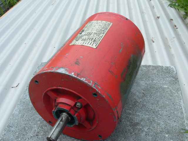
Looks like any ordinary 1&1/2 hp , but this one is fried, cooked to perfection.
Taking it apart was a breeze, I used the Zubbly no nonsense approach and
chiselled the burnt windings off.
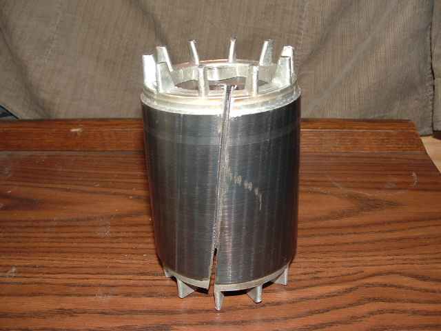
Rather than machining the rotor down I elected to remove the laminations and use the old shaft.
I cut the lams with a thin kerf blade and then slid them off of the shaft.
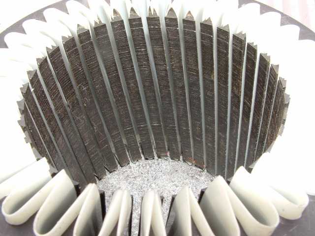
The stator is skewed ten degrees and I have installed the (Dacron-Mylar-Dacron .01") insulators.
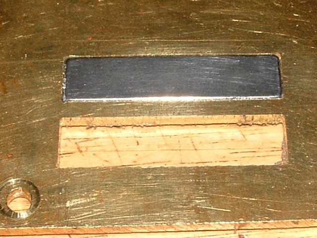
Here is the first test cuts with the WXYZ Machine. The magnet fits good the second attempt.
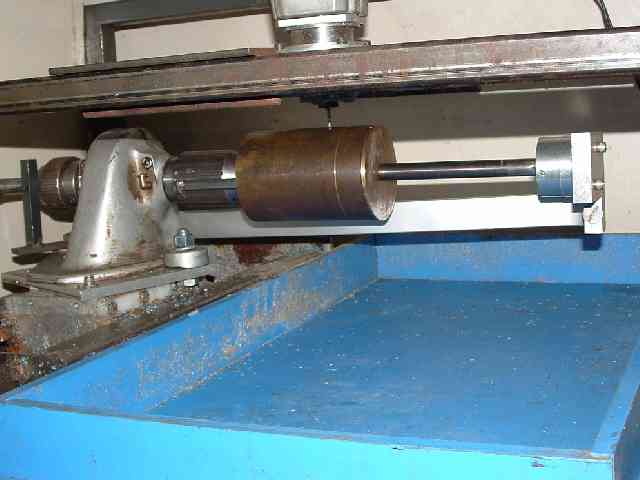
My blank cage is mounted on the horizontal indexer that was added to this old work horse last week. The indexer is geared to give me a resolution of 36 divisions.
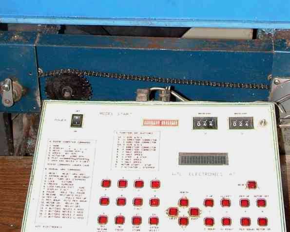
This is the A7 CNC Controller, one of Bill's early models. The backlash thumb-wheels are on the top right of the unit.
The Cut Begins. 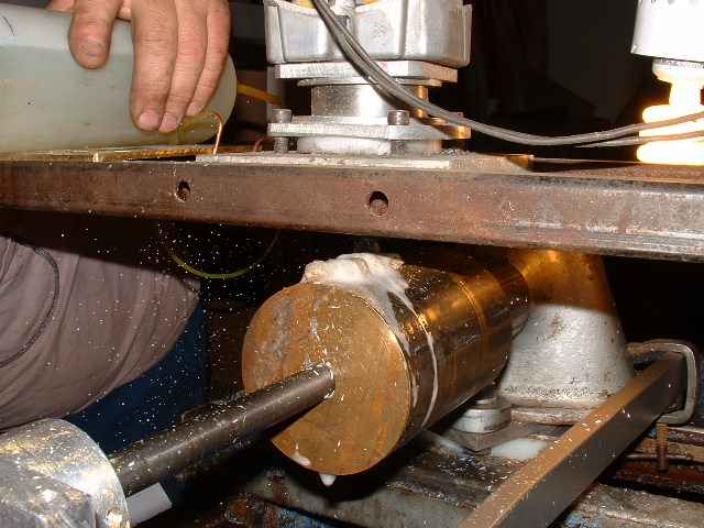
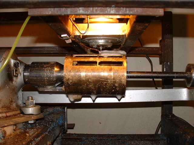
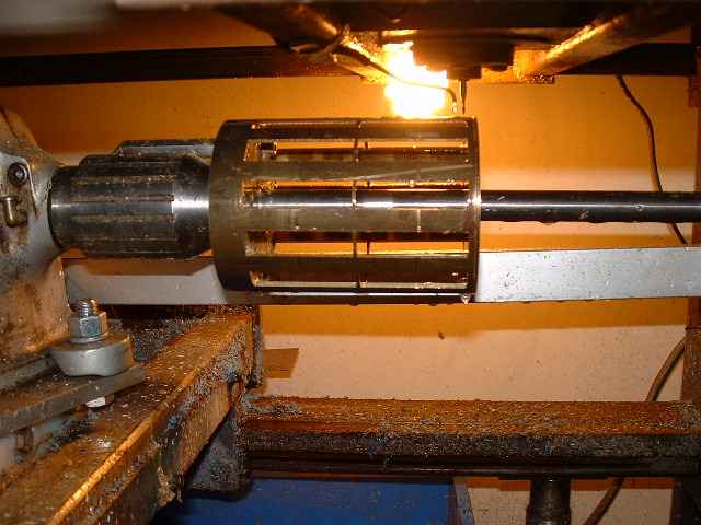 The Cut Ends
It takes almost two hours to cut the 24 magnet holes. Slower than I could, but it pays in the long run on the cost of cutter blades. They are dual flute 1/16" solid carbide, running at 50,000 rpm. I use 25 ml of standard dish soap to 1 litre of water as the cutting fluid to cool the cutter.
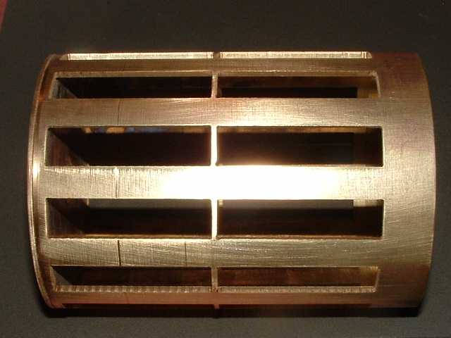
The brass pipe had it's start in life several hundred feet under the ground, as it was in it's past life a deep well pump casing. Recycled to live on.
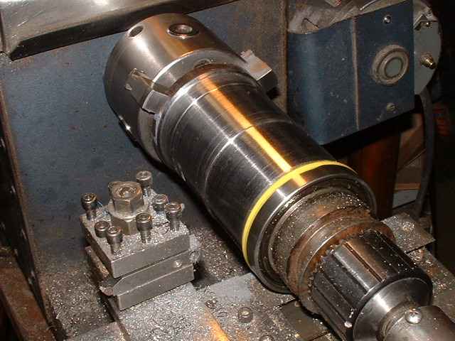
The new rotor is being machined to hold the 24, 2" x .5" x .385" N40 neodymium magnets.
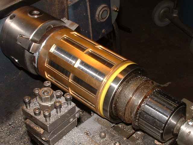
The cage is now placed over the steel rotor.
This is an ongoing project and I will continue to post updated photos.
This last picture is in keeping with my approach to this R.E. stuff.
I sometime feel like this little guy. Well fed and happy.
 Enjoy
Enjoy