Author Topic: My first Induction Motor Conversion.  (Read 10748 times)

0 Members and 1 Guest are viewing this topic.

sPuDd

  • Jr. Member
  • **
  • Posts: 51
My first Induction Motor Conversion.
« on: June 22, 2006, 05:13:53 PM »
This is the first completed stage 1 of my RE projects list, and only

occurred as a result of finding the Otherpower.com site and others like

Hugh Piggott's. Recently I spat the dummy and quit working for the

multination corporation that had me harnessed for several years.

This has given me the opportunity to finish this project step and start

on many others.


I'd just like to say "Screw corporations! You blokes ROCK :) !"


Now for the RE images I promised.


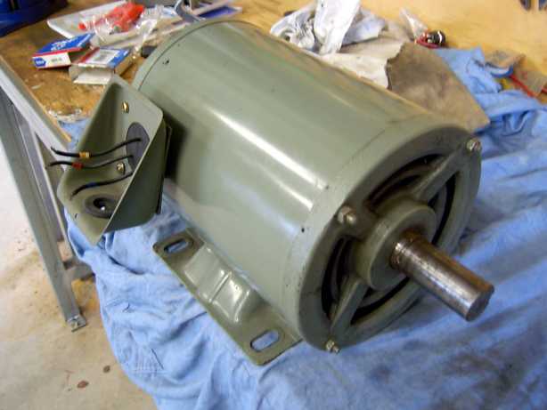
The unit is a Japanese made Fuji Electric 3hp (2.2kW) used 3phase

Induction motor. Looks like a nicely built unit. Spins freely and is a

breeze to dismantle.


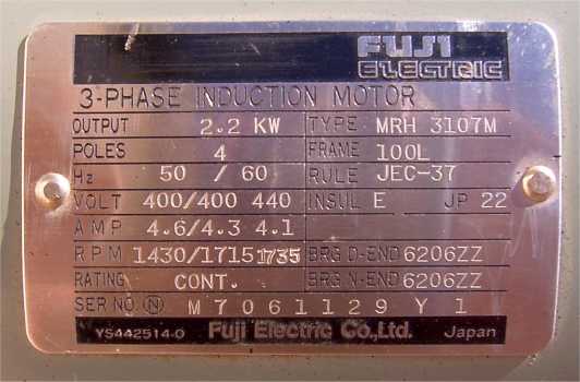
The plate shows it is a 4 pole 415V unit. It's a 36 slot, and I will be

using the existing windings after bringing out three more wires for

Star-Delta selection.


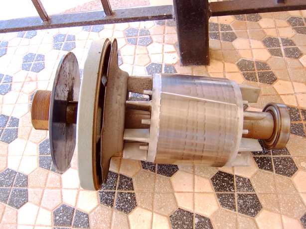
The rotor pulled out. It came with about a 125mm (5 inch) pulley

attached, and I think I might use that for the final installation.


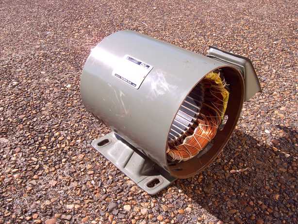
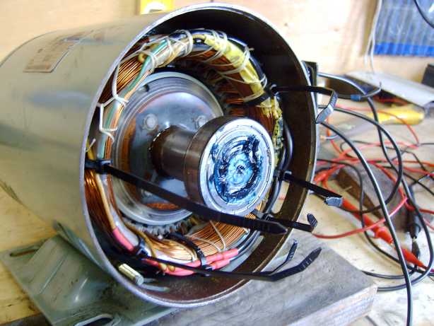
Stator with rotor removed drying in the tropical summer sun. I gave

it a good hose out, and scrub with a tooth brush as there was some

muck in it.


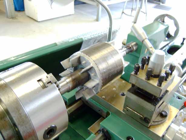
I bought a 2hp metal lathe, and had to test the rotor in it. Even before

I had unpacked it properly and put it up on its stand. :)


The first pass revealed a nice shiny rotor. I'll be using the 48 of the #18

19mm x 12.7mm (3/4 x ½ inch) Neo's from www.forcefieldmagnets.com.

So I have to machine a good deal of material off the stator to make it all fit

back together.


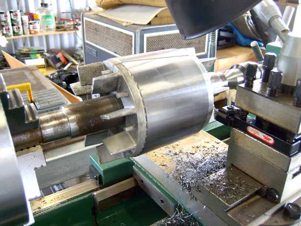
But I hit a little snag. I had to take off so much material, that the alloy fan

ends came off, taking about a dozen laminations with them. I thought that

was curtains for the rotor, but I had a think about it over lunch.


I dug up some 50mm (2 inch) fine thread metal screws, the kind used to

attach a steel roof to steel battens. I found a 3.97mm (no idea in inches)

drill bit and put pilot holes into the laminations. I then oiled the screws

and put them in with a decent electric drill. Four screws into each end, a

quick spin in the lathe and I was back in business :)


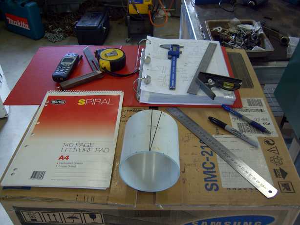
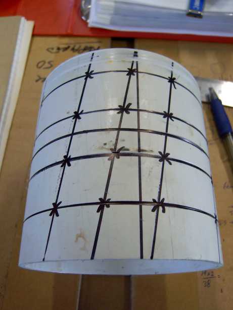
Next step was to start making a rotor cage for the magnets. As this is a

36 slot motor, it requires a 10 degree skew on the magnets. I studied the

diary postings by Zubbly in order to figure all of this out. I am but a hack

compared to the likes of Zubbly :)


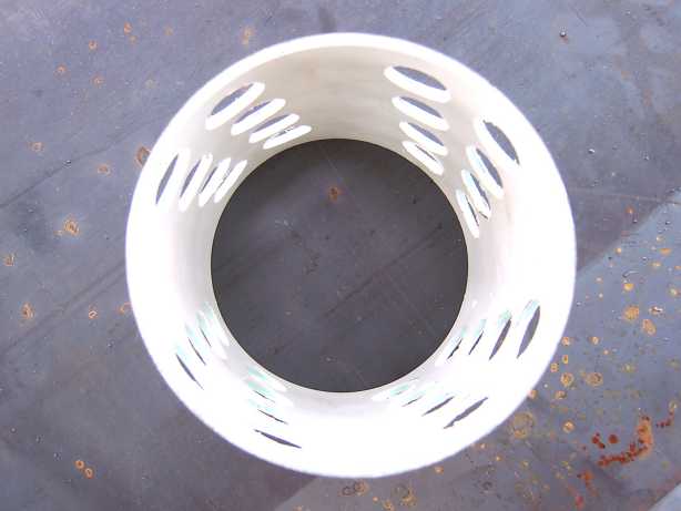
The cage is a piece of 100mm (4 inch) domestic water supply pipe.

Although not as high tech as an aluminium or fiberglass cage, it worked

well and cost nothing.


Initially, I had intended to use 3 x 4 groups of magnets for each pole.

But checks showed it would have been too much of a squeeze, and not

enough distance between opposite poles causing possible cancellations.

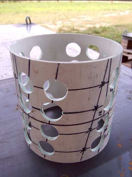
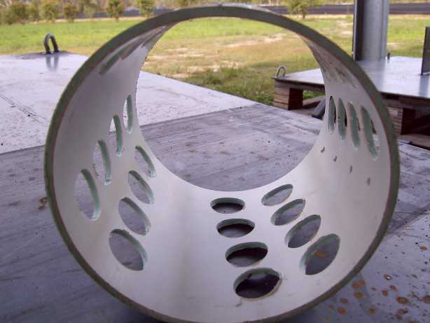
So its now 2 x 4 groups of magnets for each pole (32 magnets total).


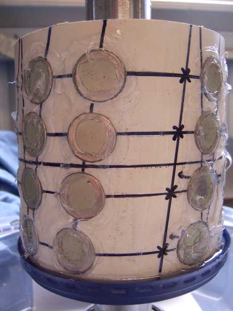
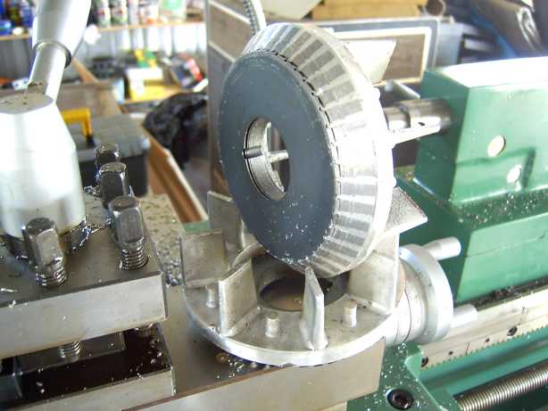
This is the part that worried me the most. Epoxy day. An old food

container lid was a nice fit for the bottom of the cage. And silicone

was used to plug and seal everything. You can see a little bit of leaking

epoxy that the lid caught. I put the rotor back into the lathe once it cured

and machined off any bits that were sticking out.


When I first added the Part A and B epoxy together, it was like trying

to mix oil and water. So I quickly cut a piece of arc mesh down to form

a stirrer and put it in the electric drill. By keeping the "stirrer" deep

inside the epoxy, I was able mix it together in less than 30 seconds and

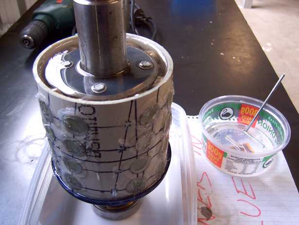
stop bubbles from forming. The rotor was stood up using one of its

bearings pushed part way onto one end. An ice-cream container formed

an emergency spill container. ( I keep all my food containers these days).


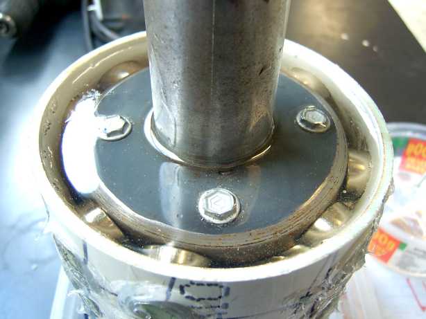
The round magnets allowed all the air bubbles to escape very nicely.

The epoxy completely covers the heads of the screws I had to put in too.

Just to be sure, I ran an orbital sander on top of the shaft for a few

minutes to bring out any last bubbles. It took about 1 hour to show any

sign of curing, and it felt very slightly warm to the touch. I hope this

slow cure will make for a very strong bond.


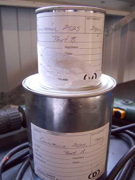
The epoxy I bought was Concresive 2525. Which according to the

confused sales guy, was probably best for metal bonding compared to

the other stuff they had. http://www.degussa-cc.com.au/resrep/resrep9.htm

I would like to try some West System epoxy on the next project. It seems

to be a favorite among the forum users here.


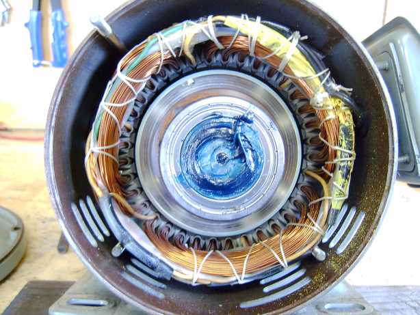
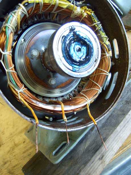
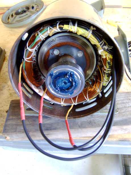
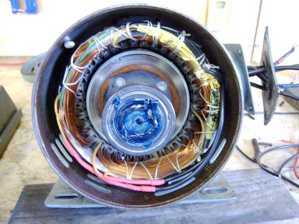
And after a week of curing in the tropical sun, I put the rotor back into

the stator with new bearings. At the bottom left corner of the stator you

can see the internal connection point for the star wiring. You can see

the three yellow wires going into it.


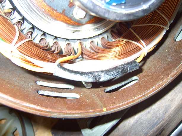
A close up of the star point connection in its black insulation.


A few snips and it was open and ready for new wires.


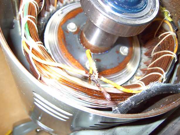
Each wire was cleaned back with fine wet-and-dry sand paper

and then with alcohol.


Three new holes were drilled into the rubber cable grommet,

and the wires fit tight.


Three new 4mm square double insulated wires, and double

heat shrink connections.


And neatly tucked in, ready for securing into place.


As any Electrician will tell you, cable ties can fix anything.

Hell I know multistory buildings that are held together by the

humble cable tie :)


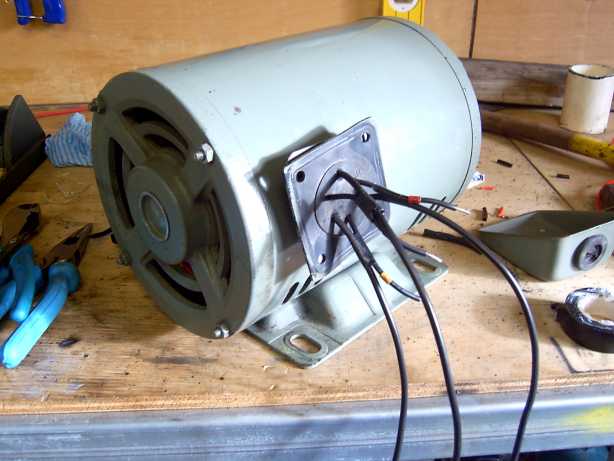
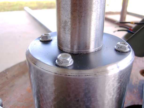
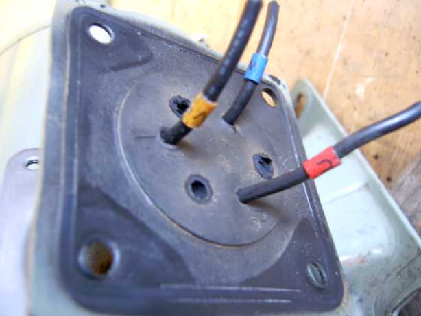
And the termination box with six wires now coming out. I also later

extended the existing three short wires to make termination easier.

Before any other tests I gave the shaft a spin by hand - very nice.

Smooth and can be spun with two fingers.


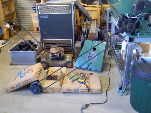
Putting the motor into the lathe chuck was more dangerous than the

setup in the picture. Trust me. And this way if all went pear shaped,

the belt would just fall off the pulley. I'm thinking about an old car

engine from a wreckers for doing this type of thing, with the whole

thing on a steel base frame so I can make infinite readings over the

RPM range.


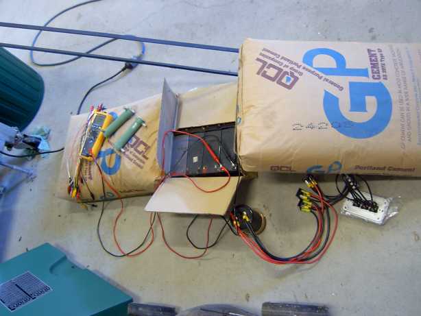
I setup three single pole switches to change between Star and Delta

while testing. The three bridge rectifiers are 1200V 35amp International

Rectifier GBPC2512A. I chose the high voltage units in the hope they

will survive an open circuit voltage condition a little better than the

usual 400V types. The big capacitor is a 400VDC 4,700uF beast from an old

heavy duty 1500VA UPS. Did I mention cement bags are a multi purpose

tool ?


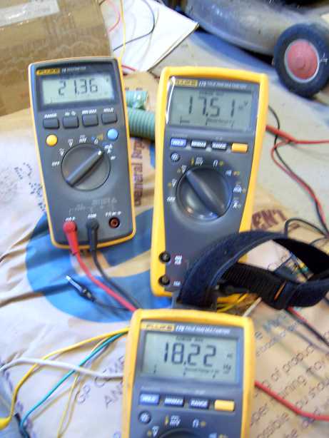
At about 540 RPM in Star into 8x 12V 7Ahr gel cells, all about half flat.

The lathe motor strained under the load, so I only ran each test for about

5 seconds and then let the motor cool off for 5 minutes.


Left meter is showing about 21 amps DC.

Right meter is showing about 17 volts DC.

Bottom meter is showing about 18Hz, which translates to about 540 RPM.

Which all up is about 350watts.


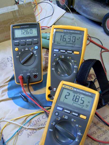
At about 650 RPM in Delta, we see about 190watts.


Left meter is showing about 12 amps DC.

Right meter is showing about 16 volts DC.

Bottom meter is showing about 21Hz, which translates to about 650 RPM.


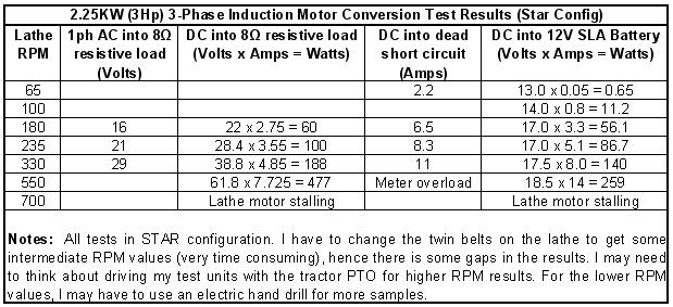
I did some tests in Star mode with the motor shaft in the lathe chuck.

It  was dangerous as there was no real way to secure the motor from

the start jolt. For your info, each stator coil is about 6ohms.


In conclusion, I'm chuffed about the whole exercise going so well.

I would call this a 500watt generator to be conservative. I think the

poles are saturated well. A large screw driver will stick to the rotor

shaft. I have 18 x magnets left over and I will use 16 of them to

make a small standard dual rotor design from scratch, with two left

for spares.


An engine/gearbox driven test bed for this and future generators is

on my project to do list.


I'm going to do a set of wood blades from the Warlock calculator a set

them for high torque but low RPM. We have about 15-20km/h

(about 5m/s) constant wind here most days, with gusts to double that.

Oh, and the occasional 300km/h Cat-5 cyclone.....  :)


I have already modified an old car hub to be the blade hub. Have

bought a 63.5mm (2.5 inch) and a 250mm (10 inch) belt pulley and

will use them in a "speed up" configuration with an MPPT controller

of my design. This should give a 1:4 up ratio and I hope to see an

average of 400-500 RPM on the generator.


Recently we took down a 16m (48 foot) fold over lattice radio tower,

and that will be the new home for the generator with a 6m (18 foot)

pole extension at the top. A total of about 22m (66 feet).


Costs:

Magnets  ~AU$300 delivered.

Motor - free

Epoxy  ~ AU$20

New Bearings ~ AU$40

Rectifiers ~ AU$18

« Last Edit: June 22, 2006, 05:13:53 PM by (unknown) »

fungus

  • Sr. Member
  • ****
  • Posts: 448
Re: My first Induction Motor Conversion.
« Reply #1 on: June 22, 2006, 01:35:45 PM »
Very good. I'd like to see how it goes with the blades on and up the tower. Certainly a lot to put in one post:-)
« Last Edit: June 22, 2006, 01:35:45 PM by fungus »

Slingshot

  • Full Member
  • ***
  • Posts: 231
Re: My first Induction Motor Conversion.
« Reply #2 on: June 22, 2006, 02:32:50 PM »
That's a very fine documentary.  Did you happen to take any pictures of the finished rotor, after cleanup?  How did you get the silicone off of everything?


Did you have any problems re-inserting the rotor into the case, ie the magnets wanting to pull the rotor over to the laminiations?

« Last Edit: June 22, 2006, 02:32:50 PM by Slingshot »

electrondady1

  • SuperHero Member
  • ******
  • Posts: 3120
  • Country: ca
Re: My first Induction Motor Conversion.
« Reply #3 on: June 22, 2006, 02:34:58 PM »
thats a wonderful bit of work. and super documentation  congrats.
« Last Edit: June 22, 2006, 02:34:58 PM by electrondady1 »

willib

  • SuperHero Member
  • ******
  • Posts: 2414
  • Country: us
Re: My first Induction Motor Conversion.
« Reply #4 on: June 22, 2006, 02:42:53 PM »
yes great project

a set of 4 foot radius blades at tsr6 should give you about 185rpm at 15 km/h

if you go with a 24 v system it should stary charging soon after 15 km/h..
« Last Edit: June 22, 2006, 02:42:53 PM by willib »
Carpe Ventum (Seize the Wind)

dinges

  • Hero Member
  • *****
  • Posts: 1294
  • Country: nl
Re: My first Induction Motor Conversion.
« Reply #5 on: June 22, 2006, 03:08:28 PM »
Very interesting and a good read!


I'm in the process of converting a similar motor as yours (3HP/2.2kW, 4 pole, 380V). See my diary.


One thing I notice that your rotor is relatively short, compared to its diameter (short & stubby; mine is taller/more slender. Was thinking at first this was a USA-thing until I realized you're from Oz).


I Like the idea of using caulk to prevent epoxy seeping through any small cracks (have had this happen on numerous occasions with other projects). Caulk could be a perfect solution, since it's usually easy to peal off again.


The lathe is exactly the same as one of mine, I think :) (but mine is over 10 years old). Turned down the rotor of my 3HP a few days ago (wouldn't even think about doing it in that small lathe, BTW. Used 'the big one' for that. It was terrible. The steel laminations (transformer steel) has a lot of silicon and this makes machining dreadful. Lots of spark, noise, red glowing carbide inserts, etc.etc. Took about 2 hours to fully turn it down, after which I could remove the remaining laminations by hand (I wanted just the axle).


As far as skewing goes (here we go again...). Did you mark out those 10degrees on that plumbing tube? Because your skewness looks like a lot, probably 10 degrees. Please check out my diary too about my pondering the skewing question.


The good thing about 3phase motors over here is that all I have seen have 6 connections to the outside world; both start and end of each phase are available at the junction box. So there's no need to bring out the hidden star point to the outside world, it's already there. That way, the motors can be wired for 220V 3phase and 380V 3phase by means of a 3 jumpers.


As to output, 500W is a lot but personally, before I started my conversion, I had expected that such a motor should be able to deliver much more, perhaps 1kW, without rewinding. Good thing my expectations are corrected before my project is finished. Still, a very nice generator and solidly build. See you've replaced bearings too. Excellent. You've definitely put some thought into it all.


>Costs:

>Magnets  ~AU$300 delivered.

>Motor - free

>Epoxy  ~ AU$20

>New Bearings ~ AU$40

>Rectifiers ~ AU$18


Homebuilt electricity ~ PRICELESS


(BTW, please tell which buildings are held together by tiewraps so that I can avoid entering them :)  )


Peter.

« Last Edit: June 22, 2006, 03:08:28 PM by dinges »
“Research is what I'm doing when I don't know what I'm doing.” (W. von Braun)

WXYZCIENCE

  • Sr. Member
  • ****
  • Posts: 355
Re: My first Induction Motor Conversion.
« Reply #6 on: June 22, 2006, 03:12:34 PM »
Well done, I am on slow dial-up and the posting was excellent. I could read your text as the pictures loaded. Grasshopper, it is your time to go out into the world and teach your art. :-) Can't wait to see more. Joe
« Last Edit: June 22, 2006, 03:12:34 PM by WXYZCIENCE »

dinges

  • Hero Member
  • *****
  • Posts: 1294
  • Country: nl
Re: My first Induction Motor Conversion.
« Reply #7 on: June 22, 2006, 03:17:09 PM »
4ft seems awfully small for such a motorconversion. I was thinking with mine more in the order of 10ft.


The way I try to match prop to genny is by first matching power available from the prop (at your desired furling windspeed) to the max. power that the genny can deliver. The result is the diameter of your prop.


Then, one has to take into account the required RPMs for the genny. By changing TSR of the prop, you can get the desired RPM at cutin windspeed.

« Last Edit: June 22, 2006, 03:17:09 PM by dinges »
“Research is what I'm doing when I don't know what I'm doing.” (W. von Braun)

asheets

  • Sr. Member
  • ****
  • Posts: 368
Re: My first Induction Motor Conversion.
« Reply #8 on: June 22, 2006, 03:22:53 PM »
So, you didn't rewind at all?  That's the kind of thing I like to hear; that's the part I don't look forward to, and am looking at choosing a motor specifically to avoid that.  Can you share a little more detain on that part of it in your next diary?
« Last Edit: June 22, 2006, 03:22:53 PM by asheets »

willib

  • SuperHero Member
  • ******
  • Posts: 2414
  • Country: us
Re: My first Induction Motor Conversion.
« Reply #9 on: June 22, 2006, 03:58:27 PM »
 four foot radius

« Last Edit: June 22, 2006, 03:58:27 PM by willib »
Carpe Ventum (Seize the Wind)

dinges

  • Hero Member
  • *****
  • Posts: 1294
  • Country: nl
Re: My first Induction Motor Conversion.
« Reply #10 on: June 22, 2006, 04:05:25 PM »
Oops... Tiny detail I had overlooked :)
« Last Edit: June 22, 2006, 04:05:25 PM by dinges »
“Research is what I'm doing when I don't know what I'm doing.” (W. von Braun)

zubbly

  • Sr. Member
  • ****
  • Posts: 371
Re: My first Induction Motor Conversion.
« Reply #11 on: June 22, 2006, 06:47:49 PM »
hi SpuDd,


excellent job!


sometimes i have found in the past that i may have to use 1/2 inch diam mags instead of 3/4 diam so i can pack them closer together in a givem space and get more mag in a given area. you did an excellent job just the same!


just a question, did you calculate the total cubic inch of mag material in it and see what wattage it will give under load at approx 600 rpm?  i ask this just to help confirm or find that it is a close constant for approximating puropses when forecasting output.


zubbly

« Last Edit: June 22, 2006, 06:47:49 PM by zubbly »

sPuDd

  • Jr. Member
  • **
  • Posts: 51
Re: My first Induction Motor Conversion.
« Reply #12 on: June 22, 2006, 10:26:01 PM »
Thankyou to all who have posted a reply to my diary.

The positive feedback I have received is quite uplifting... THANKYOU :)


Oh, it took about 6 hours to put the whole document together

in MS Word and then insert it on the forum and test everything.

I know its a little long, but by spacing everything I hoped

to allow time for the 1meg worth of tasty pictures to load

while people were reading from the beginning. Each pic is

generally less than 40Kb, and still looks fine.


OK, answers to questions:


Slingshot, - See pics below.


The silicone just peeled off like a banana skin. It seems to be

the way to do it. I made a sort of rounded nose on the drive end

that I hoped would make insertion into the stator easier. I put

thick welding gloves, lined up and let 'er go! Was far easier

than I thought. Once in, trying to get the bolts/holes to line

up was fun, but by using the motors own weight offset on a block

of wood it wriggled in.


Willib & Dinges,

I'm enjoying playing with the Warlock blade calc a little too much.

It might fall off at this rate :) Keep in mind I'll be extracting power

via an MPPT. Hence the "resistive" load testing is closer to my final

requirements & calculations. It will also switch Star/Delta for best

performance. Low RPM with high torque is my main guide. I like it slow.


Dinges - Not sure why the rotor is "stubbier". I know that even after

loosing about 10mm of laminations and ends, the magnets just barely

poke out a few mm past the stator laminations. Maybe it was made that

way to have more torque as a motor ? Like a bigger engine flywheel ?

Silicone/Caulk also allows for um... a poorly drilled magnet hole :)

The lathe is small compared to... a bigger one, but one must start

somewhere. I use cutting coolant on the tip and job which makes it all

quite a refined affair. Yes, I can't bite off huge chunks of steel

without breaking stuff, but that's not my style - I lathe to clear my mind :)

10 degrees of skew - yup. Looks like more, but I think its the black

pen on white tube that makes it look that way. As per Zubbly's design.

Most motors here have 6 wire boxes too, not sure why this one did not...

PS: All buildings held together with cable ties are Govt' - so no loss :)


WXYZCIENCE,

I have a confession master OB1, the next diary posting is my conversion

failure... you might make me stand in the cold holding bricks soon :)


asheets,

um, the motor was given to me free, and as it was an Induction motor,

4 pole, decent size & 3 phase - it was accepted :) I hope to find a

similar or bigger one next time, maybe with more poles for a lower RPM.


Zubbly, (my main man :)

um, I kinda screwed up on figuring how many mags I could fit on the rotor.

As you saw, I went from 3x4 rows to 2x4 rows. Performance seems at least

close to yours though. Calculations - not my strong point. I seem to be

better able to make a mental guesstimate and wing it. I probably could

have used 1/2 inch mags and packed them in. I think I was trying to keep

them within the tooth spacing and stator length. Oh, and magnet cost. Its

about +AU$100 to ship them to SkippyDingoLand here on the banana boat :)

PS: You are the reason I have had a go at this - THANKYOU, for the time

and wisdom you give to this forum. You are very highly regarded & appreciated

by all.

« Last Edit: June 22, 2006, 10:26:01 PM by sPuDd »

dinges

  • Hero Member
  • *****
  • Posts: 1294
  • Country: nl
Re: My first Induction Motor Conversion.
« Reply #13 on: June 22, 2006, 10:57:18 PM »
I have the same problem as yours, of not being able to fit as many magnets on as I would like. One solution is to 'offset' the magnets to each other; for example, you now have 2 rows of 4 magnets. Perhaps 3 rows, with 4-3-4 magnets would fit, with the middle row with 3 magnets offset a bit w.r.t. the outer rows. Even with this trick I can't get 3 rows in my conversion. Another idea could be to use slightly smaller magnets in the middle row. AFAIK, there's no law that says all magnets should be equal size. So perhaps the wasted space between magnets could be filled with smaller magnets.


This 2nd trick I won't try with my first conversion, but might be of use to other potential motor converters.


So for you lathing is a Zen-thing eh? Just turned down my 2nd rotor (for the 130W conversion) and relaxing is the last thing I'd call it. But perhaps I cut a bit more, ehm, aggresively :) Still got the chips in my hair...


Peter.

« Last Edit: June 22, 2006, 10:57:18 PM by dinges »
“Research is what I'm doing when I don't know what I'm doing.” (W. von Braun)

sPuDd

  • Jr. Member
  • **
  • Posts: 51
Re: My first Induction Motor Conversion.
« Reply #14 on: June 23, 2006, 02:56:24 AM »
I wonder Dinges, if say tall thin rod like magnets would be worth

a try. Example the #16 or #26 rod magnets from Wondermagnet.com.

1/4 inch dia. x 1/2 inch long -or- 1/8 in X 3/8 in long.


They would need a thick walled cage to hold them straight until

epoxy had set. Or a precisely drilled nylon rotor bush pressed

onto the shaft. If each hole drilled was so tight you had to

mechanically press the magnets in....  hmmm. Got me thinking.


Each magnet would be so close to each other that you could almost

cover the entire pole.

Should be easier to handle - less blood and four letter words.

The small magnets are cheap.

Nylon is easy to machine.

Would save on epoxy.


Interesting...

« Last Edit: June 23, 2006, 02:56:24 AM by sPuDd »

Countryboy

  • Sr. Member
  • ****
  • Posts: 269
Re: My first Induction Motor Conversion.
« Reply #15 on: June 23, 2006, 01:48:34 PM »
Hi Spud,

  Neo magnets are very brittle.  I don't know how strong they are physically.  Attempting to press the magnets into place might result in magnets that crumble under the pressure of the press.
« Last Edit: June 23, 2006, 01:48:34 PM by Countryboy »

commanda

  • Hero Member
  • *****
  • Posts: 731
Re: My first Induction Motor Conversion.
« Reply #16 on: June 23, 2006, 03:43:19 PM »
with an MPPT controller of my design.


Spud, really nice write-up. I do know just how much effort it takes to produce really nice documentation.


I'm also working on MPPT, and interested in sharing ideas.


Amanda

« Last Edit: June 23, 2006, 03:43:19 PM by commanda »

sPuDd

  • Jr. Member
  • **
  • Posts: 51
Re: My first Induction Motor Conversion.
« Reply #17 on: June 24, 2006, 06:07:07 AM »
G'day Amanda,


I've looked at your cct's and have "stored" a few of them for

little later projects :)  Once I get this main unit airborne

I'll have an animal on which to make wild field tests. As soon

as I get started, you can be assured I will post a diary with

LOTS of very tasty info :)


I know the KISS principle is the aim of this forum, but I have

a nasty tendency to buck the system. Its that, or I build a

nude bomb...


Perhaps I should make a "Soft" and "Hardcore" version of

each design to allow everyone to have a go.


sPuDd..

« Last Edit: June 24, 2006, 06:07:07 AM by sPuDd »