Author Topic: A poorman's motor conversion  (Read 4495 times)

0 Members and 1 Guest are viewing this topic.

Smithson

  • Jr. Member
  • **
  • Posts: 75
A poorman's motor conversion
« on: June 03, 2006, 07:19:15 PM »
This is a motor conversion from plans found in a magazine article from 25 to 30 years ago.  The author's machine was rated at 1800 watts into a 36 volt battery bank.  At 600 rpm he measured forty five volts and forty three amps.  All he was trying to do was emulate the M Jacobs wind plant, with the variable pitch and folding tail.  He was shooting for full output at 300rpm, but had to settle for a 1:2 geared step-up.

My alternator bench tested at, measuring at the output of 3 full wave rectifier's 75.5 volts dc [open voltage] and 48.5 frequencies across two of the phases, or translating 75 volts at 727 rpm.  [rpm = 15*48.5][12 volts for every 115 rpm]  I don't know if that is good or bad.  It is a simple, good way to convert a motor but is not a perfect way.  

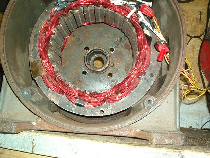
I tried to follow the plans as much as possible.  The plans call for leaving every other slot empty.  I did that.  You might do better to fill every slot and use smaller width magnets.  Or I could, on this one, wind another 3 phases, since every other slot is empty and end up with 2 three phases alternators. I just followed the plans.  Anything beyond that might not be electrically possible.  The only design changes made were that the author had a 36 slot motor with six wound fields, and used two 15awg magnet wires in hand.  To be fair to him he accomplished his output with only 18 coils.  With my 48 slot motor you "wind up" with 24 coils and eight two inch wide magnets for the poles.  

You don't know what you are getting looking at the outside of a motor.  Go with what you get.  I figured that with ceramic "brake drum" magnets there would not be that much current and 16awg wire, two in hand, was "good enough".  There are fourteen turns of 16awg wire for each coil.  I might add though my motor was not the best candidate for motor conversion as you "need a motor with a rotor diameter of at least eight to ten inches".  [This is the author's opinion only].  [He felt that to have maximum output you needed a very powerful wound rotor with 500 turns of 16 or 17awg wire for each of the poles].  Looking back now I think he could have achieved his goal if he had filled every slot on his conversion.  Again take what you can get.  This motor is only seven and three sixteen inches across the open stator.


The magnet needs to be less than the width of a coil by at least one slot.  For two inch wide magnets I wound slots one to seven, to fit the magnets, and the plans.  Then wind slots seven to thirteen, etc.  Eight coils per phase, twenty four coils in all.  The slot that each coil leg finishes in also shares that slot with the first coil leg for the next coil in that phase.  So as you wind around the stator the last coil leg of phase one shares the same slot that coil one for that phase started in.  Each adjacent coil is wound in a reverse direction from the previous coil.  [Clockwise, counterclockwise, etc].  With my setup [again to match the available magnets width] phase two is started by skipping a slot and starting phase two in slots three to nine, nine to.... etc.  Phase three again skips a slot and starts in slot five.  When you finish solder the finishes of phases one and three to the start of phase two in a star configuration.  This keeps the 120 degree spacing needed for a three phase alternator.  Otherwise the output will suffer across one of the phases. [5vac less at 127 rpm on mine]


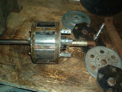
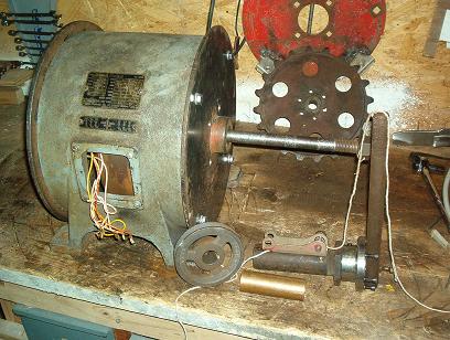
The rotor end plate is made from a ¼  steel plate with the corners cut off.  {As shown in the photographs]  I used four of these octagons with a two inch center hole and a four bolt trailer hub pattern.  By inserting all thread bolts and nuts [brass or stainless steel is nice] the two octagon end plates are held in alignment and magnet backing plates are welded under the lip to the octagon end plates.  Leave the all threads in place and the other two plates with your shaft size hub can just be bolted in place, but first have aluminum pulley's to butt against the ends of the magnets.  With this setup you can interchange any shaft size at any time you want.  The magnets are glued to the backing plates and the two aluminum pulley's [again with the four bolt pattern] hold them from each end.  My magnets are held in place on the side by lawn chair aluminum tubing pressed flat and bent in a vise to fit the angle.  Then it is fastened to the rotor by drilling and taping.  The whole rotor unit was set in a form and polyester resin poured in the cracks.

    There is no skewing.  I can take the rotor and turn it with my thumb and forefinger.  It feels like those farm duty motors you see in an agriculture store. The odd look is a result of bar iatric surgery.  I tried to cut out the weight.  The end bells weight twenty five lbs each and the rotor shaft adds 16 lbs.  The new endplates were from a dumpster, the 7/8 shaft from a junk side sickle mower, the roller and thrust bearings from an old Ford two row corn picker.  I can go back to the original shaft with a two inch hub.     


« Last Edit: June 03, 2006, 07:19:15 PM by (unknown) »

The Professor

  • Newbie
  • *
  • Posts: 33
Re: A poorman's motor conversion
« Reply #1 on: June 03, 2006, 01:43:55 PM »
 Could you please give a description or graphics of his variable pitch mechanism.

     Thank You,    The Professor
« Last Edit: June 03, 2006, 01:43:55 PM by The Professor »

Mike Cross

  • Newbie
  • *
  • Posts: 13
Re: A poorman's motor conversion
« Reply #2 on: June 03, 2006, 03:43:57 PM »
Is there some way I could get a copy of these plans?  It would be interesting to see what the output would be with the newer stronger magnets now available.


Thanks

« Last Edit: June 03, 2006, 03:43:57 PM by Mike Cross »

zubbly

  • Sr. Member
  • ****
  • Posts: 371
Re: A poorman's motor conversion
« Reply #3 on: June 03, 2006, 07:06:57 PM »
hi Smithson!


nice work.  thanks for showing anyone can do a rewind.


hope it works out good for you.

what size prop are choosing for this unit?


zubbly

« Last Edit: June 03, 2006, 07:06:57 PM by zubbly »

Smithson

  • Jr. Member
  • **
  • Posts: 75
Re: A poorman's motor conversion
« Reply #4 on: June 04, 2006, 09:54:23 PM »
    To the professor.  Jacobs had two variable pitch governors.  A flyball governor where a flyball weight moved a central gear which in turn moved all 3 blades at the same time and a later blade actuated governor where the weight of the blades moved out on a blade shaft with increased speed and feathered by moving a spider back.  I don't know which governor the writer used.  The first photo above shows my idea for a blade governor.  With 3 blade shafts [perpindicular to the main motor shaft] 120 degrees apart a wire rope [3/32?] would come down the back of the blade [which has a blade tube in it that slides on the blade shaft] go thru a pulley attached to a 1 1/4 plumbing iron pipe with a 1 3/8 OD bushing inside.  [Shown in the photo][ The string represents the wire rope.]  Then the end of the wire would attach to a revoling fixed pulley on the motor shaft.  As the blade goes out with centrifagal force the fixed length wire rope slides the pulley arrangement back.  A second wire would attach to the moving pulley and attach to the blade so that as the moving "spider" pulley moves back it would pull each of the blades to a steeper angle.  It is a take off on the Jacob's blade actuated governor and would likewise use a heavy spring to pull the blades back to home position as it slows down.  I havn't tried it.

    Mike Cross.  The article was pretty concise.  Two pages.  The wiring paragraph is the exact way it was explained in the article.  The rest of the article had to do with making a wound rotor which doesn't apply.  He later sent me a letter which mostly deals with electrical theory and a voltage regulator which again doesn't apply.  NEO magnets would cog. They might even saturate the laminates if the backiron was not big enough.  You can't turn them down, and to build this with every slot you would need over 210 dollars in wire and 32 of those 2x1x.5 neo mags to make 16 poles.  And you would have to hold them in place as you put them end to end.  Not easy. If you look at the ceramic magnets on Forcefield they are listed as grade 8.  On top of that the physical size of them is 6 times bigger than the 2x1 neo.  I wonder if on a day to day energy producing basis the neo magnet on a radial conversion would be worth it in a cost benefit ratio.  I don't know how to get a private email address on this board now.  The winding is a concentrated winding from the book "Industrial Electricity".  Might be found at the library.

    Zubby.  I havn't got as far as a blade.  I was hoping someone would tell me if it is worth using as is or should I rewind the stator.  I feel uneasy about putting a 200lb motor 50 feet up.  And to put it up with the weight off center as the side facing machines are is even worse.  All I have is a 40 foot telephone pole.  Would the wind turn it sideways being that heavy with a pipe in a pipe?  What size blade do you suggest?

     Eveybody thanks for the comments.
« Last Edit: June 04, 2006, 09:54:23 PM by Smithson »

hiker

  • Hero Member
  • *****
  • Posts: 1661
  • BIG DOG
Re: A poorman's motor conversion
« Reply #5 on: June 04, 2006, 10:33:35 PM »
looks great..

just a question--where did you find ceramic brake drum mags???

seems like thay would work great for a brake drum alt..
« Last Edit: June 04, 2006, 10:33:35 PM by hiker »
WILD in ALASKA

asheets

  • Sr. Member
  • ****
  • Posts: 368
Re: A poorman's motor conversion
« Reply #6 on: June 06, 2006, 09:57:13 AM »
What was the original article?  Author, magazine name, volume number, pages, etc...  thanks...
« Last Edit: June 06, 2006, 09:57:13 AM by asheets »