OK, here we are gonna deal with mainly the process of converting the rotor to a permanent magnet rotor. We will be using multiple magnets to form each pole and they will be held in place with what i call a magnet cage. I will refer to different diagrams of the rotor as well as the stator to get the point across as to how the process effects the rotor and also the stator.
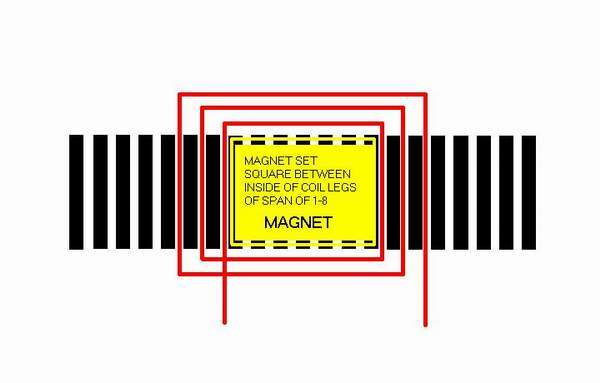
first we have a look at how the magnets match with the stator winding we learned of in part #1.
here is a diagram showing how the magnet would normaly sit in position with the winding but without any skew. without a skew, the cogging force is very strong and makes start up very difficult.
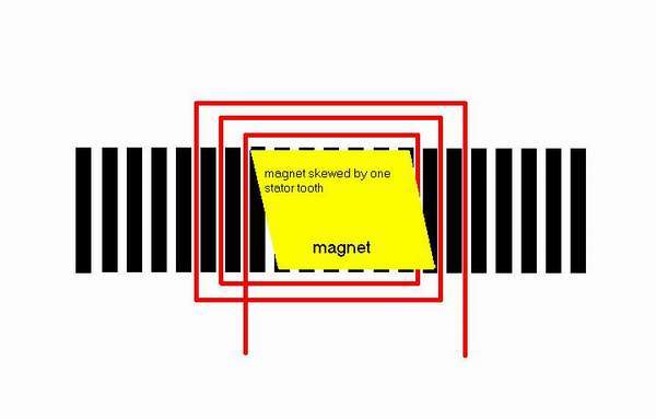
here is how the magnetic pole pieces should sit with "skew" which will in most cases completely or nearly completely eliminate the cogging effect. Complete elimination can be acheived with a one piece magnet cut with a skew ( but i have never seen a magnet offered like this )
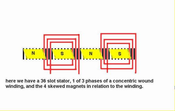
here is another diagram showing how all 4 magnet poles would line up with just one phase of the three phase winding
I will now explain best i can on how to construct your permanent magnet rotor. the methods i use works well for me and i have achieved excellent results using it. i chose to use round magnets for the simple reason it is easier to make a round hole that will be basically leak proof when you pour in the resin to bond all together. Yes, square or rectangular magnets would be a more effective magnet pole, but i have not put much effort into making this process simple with square magnets.
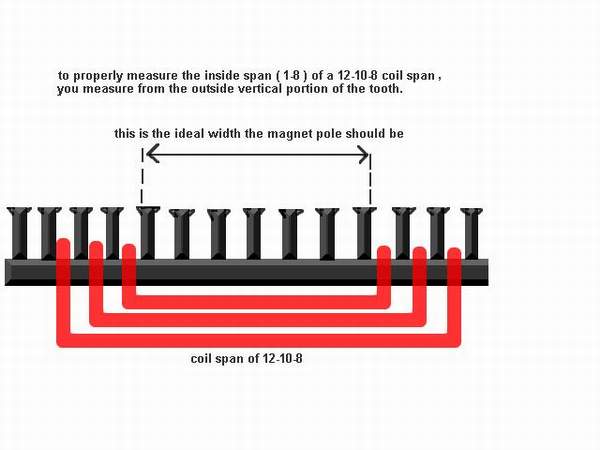
here is a diagram showing where to get the proper measurement for the width of the magnetic pole. the length of it is simply the length of the stator lamination set.
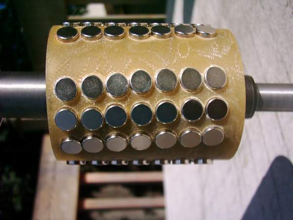
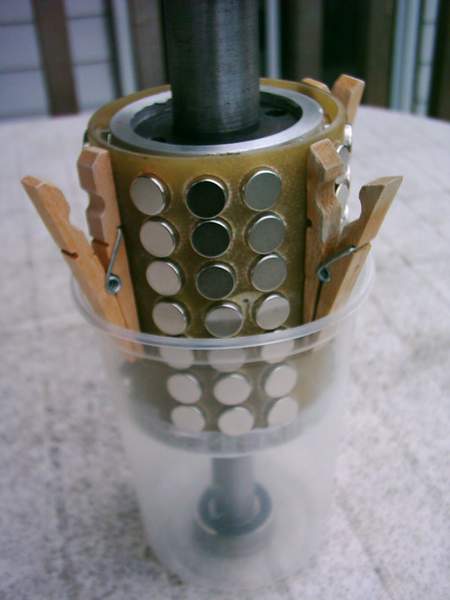
we will use the 2 hp i have just done for an example. it required a magnetic pole piece 3 7/8 inches long by 2 inches wide. i made the pole with 21 magnets per pole, total 84 magnets, 4 poles in all. i used 3 rows of 7 magnets, 1/2 inch round by 3/8 inch thick.
here is a pick of it
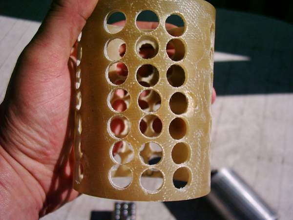
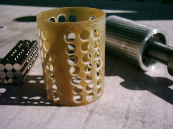
the length of the cage should be approx 1/2 - 3/4 inch longer on each end of the magnets. basically it overlapps somewhat onto the aluminum end rings of the rotor. the diamater of the cage should be approx 3/16-1/4 inch smaller than the original diamater of the rotor. it will end up just under the outer edge of the magnets. the actual thickness of the cage will be about 1/16 of an inch. the larger the cage and the longer the magnets, you may increase the thickness of the cage more. after you figure out the diamater and length of the cage, you will use a piece of platic pipe ( ABS, PVC ) for the inside diamater of the cage. turn down in a lathe the diamater of the pipe if you must and sand smooth. i then use a release agent all over the pipe, or you can use one layer of wax paper to cover the pipe. you then build up layers of fibre glass cloth approx one inch longer on each end more than what you will need and keep wrapping layers until the thickness is a little more than what you need. you then machine the layered pipe in a lathe until the fibre glass is at the diamater that you need. then cut to length between both ends of the cage and twist the cage off the pipe. you now have your cage ready to mark out for the mags and drilling.
here is a pic
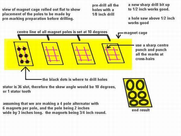
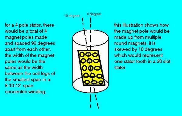
for a four pole, 36 slot stator, you will want to skew the magnets by 10 degrees, or 1 stator slot. cut out a piece of cardboard the same diamater as the cage from a cerial box, use a protractor to mark 0 degrees, 10 degrees, 90 degrees, 180 degrees, and 270 degrees. then transfer the marks to one end of the cage. use a square and draw a line from the 10 degree mark to the other side of the cage. on that side of the cage, place the cardboard with the 0 degree mark on the 10 degree mark transfered from the other side. now mark out the 0,90,180 and 270 degree marks. now use a straight edge from one 0 mark on one side to the other 0 mark on the other side of the cage. do this with the rest of the angle marks. you now have the centre of the four poles marked out ready to be used to lay out the pattern of the magnets.
heres a pic
another pic with respect to the whole rotor
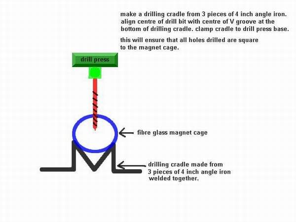
here is a simple to make aid for properly centering and drilling the holes in the magnet cage
the rotor must be turned down, and you must decide on the width and length of the mags. basically, you want to use the longest mags possible. as an example, i will use the 2 hp i just made. i used 3 rows of 1/2 wide mags to make the 2 inch wide pole piece. the two outside rows will be 2 inches apart on the outside with the third row in the middle of the other two. that leaves 1/4 inch between the 3 rows. but take note that they will be much closer together and almost touching where they sit on the turned down rotor. i suggest you draw to scale on a paper and make sure that all will fit before machining the rotor down.
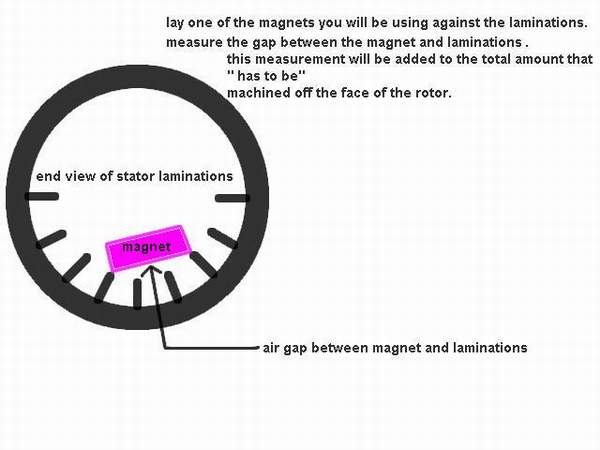
there is another consideration you must take into account before machining the rotor. if you take one of your mags and sit it on the laminations of the stator right at the edge, you will see a very small gap that must be added to the total of the rotor material removal.
here is a pic
the original measurement of the diamater of the rotor should be done with a micrometer.
we will assume a 4 inch rotor for calculations of how much to remove.
3/8 inch long magnet times 2 ( 2 sides of the rotor ) ---.75 inches
gap between magnet and laminations .o27 inch times 2 ---.054 inches
magnets not sitting square on rotor do too
improper drilling and other inconsistancies ---.025
_
TOTAL .829
rotor----4.000 inch
minus .829
____
Turn rotor diamater too: 3.171 inch
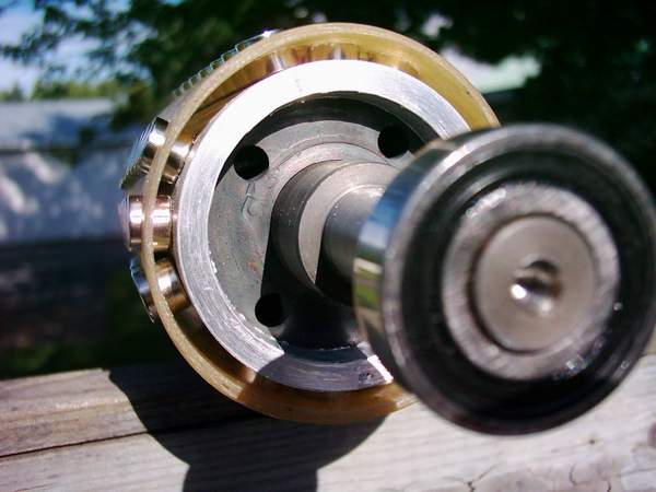
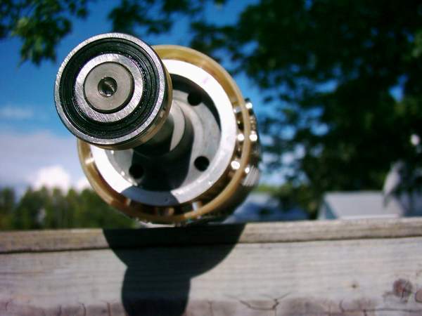
here is a pic of the turned down rotor, magnet cage, and magnets ready to be installed.
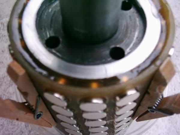
sit the rotor on the inside of the cage and insert a couple of mags into the ends of each pole. the mags will be snug fit, and you will have to adjust the centering of the cage on the rotor so that the mags lay between the aluminum end rings and that the rotor is in the centre of the cage. be sure that each pole is of the opposite polarity to the next beside it and that all mags in each pole are of the same polarity. the magnet poles will be N,S,N,S..one little trick i do is to put all the mags together in the form of a bar without any of the packing spacers that they come with. i then use the bar to get a grip to push each magnet into place. i then slide the bar onto the next hole in the same row and at the same time push down and to the side to get the next one in. it takes a little practice, but you will get used to it quickley.
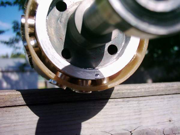
here is an end view of the rotor, cage, and mags installed showing the spacing of the mags on the rotor and where the cage sits in relation to the rotor and mags
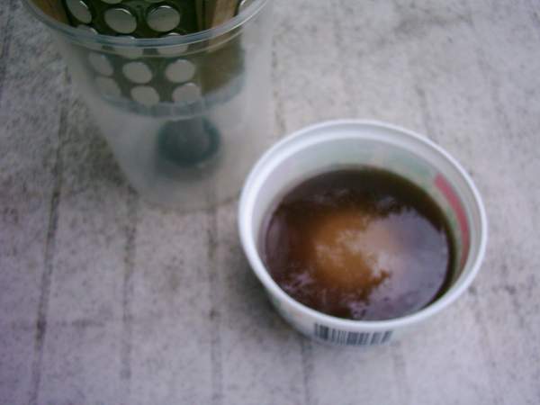
you now have to block or "dam one end of the rotor so that fibre glass resin can be poured into the rotor with out leaking. if you do get a small leak, just keep pouring until the resin sets. try to only pour in one spot as this will let the resin rise from the bottom up and you will not have any air bubbles.
i just cut a ring from some plastic container lid and scotch tape it into place tight against the magnet cage and the aluminum end ring. this seals one end to keep the resin in and is easily removed once the resin is hard.
here are some pics

there you have it, a completed rotor ready to pump out some watts for ya 
hope you enjoyed this post on rotor construction. there will be one more post to cover a complete rewind process and how to determine the proper turns from a bare stator to using the existing winding to design the new one from.
zubbly
